Chapter 7. Designing Deployable Infrastructure Stacks
The preceding chapter described several levels of infrastructure components, including code libraries, infrastructure compositions, and infrastructure deployment stacks. I recommended starting by implementing a single level of infrastructure component, then evolving it into multiple levels as the system and the teams that build and use its infrastructure grow in complexity.
Deployment stacks are the fundamental unit of design for Infrastructure as Code, because they are the unit that Infrastructure as Code tools provision. So these are the first type of component to explore.
An infrastructure deployment stack is an architectural quantum, defined as “an independently deployable component with high functional cohesion, which includes all the structural elements required for the system to function correctly.”1 In other words, a stack is a component that you can change and deploy without needing to deploy other components, even ones with dependencies on it.
When you change one element of a stack with multiple elements, you need to test the entire stack to be confident everything still works as expected. Because deployment tools work at the level of the stack, any element it defines could potentially be changed, even if you haven’t directly modified it. The more elements are in a stack, the longer it takes to deploy it, to test it, and to troubleshoot and fix it. The effort to manage a change tends to grow exponentially with the number of elements in a stack.
A smaller stack keeps the immediate scope of the change smaller, so it takes less time to develop, test, troubleshoot, and fix. A small scope means a small loop to change, which means changes can be made more quickly and more frequently. Applying rigorous quality control on smaller pieces is also easier: testing goes faster, and failing tests are much quicker to address. So changes are safer, making it easier to keep a high level of quality.
However, smaller deployables push some of the complexity of a system into the integration points between them. Therefore, while the feedback loop to test and deliver changes to one stack may be very fast, the risks from those integrations need to be managed.
The goal of design is not to break infrastructure into the smallest possible deployable pieces. Instead, the goal is to organize infrastructure into the pieces that balance various design forces (as discussed in “Design Forces”), to achieve the relevant outcomes (as discussed in “Strategic Goals and Infrastructure as Code”).
This chapter describes two sets of design patterns for infrastructure deployment stacks. The first set of patterns is used for choosing the size and composition of deployment stacks for the infrastructure you need to create and manage. The second set of patterns is used to implement multiple copies of the same essential infrastructure, as when creating multiple environments (for example, development, staging, and production environments).
Patterns for Sizing and Structuring Stacks
Given a set of infrastructure resources that support one or more workloads, how should you group them into deployable infrastructure stacks? This question comes down to the considerations and forces discussed in Chapter 5, such as cohesion and coupling. However, some common patterns emerge for grouping infrastructure into deployable units based on aligning them to groupings of the workloads that run on them.
This list gives a brief summary of some patterns, each of which is then defined in more detail afterward:
-
A Full System Stack defines all the infrastructure for a system in a single deployment stack.
-
A Monolithic Stack is a deployment stack that has become too large to manage effectively.
-
An Application Group Stack defines all the infrastructure for a group of related applications and services in a single deployment stack.
-
A Single Service Stack defines the infrastructure for a single application in one infrastructure stack.
-
A Micro Stack breaks the infrastructure for a given application or service into multiple deployment stacks.
-
A Shared Stack provisions a subset of infrastructure for use by multiple workloads.
Full System Stack
The Full System Stack pattern defines all the infrastructure for a system in a single deployment stack, as shown in Figure 7-1.
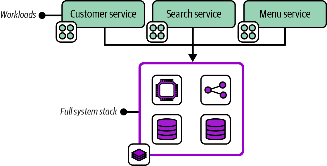
Figure 7-1. A full system stack with the infrastructure for four workloads
Motivation
Managing infrastructure in a single stack avoids the overhead of deploying, testing, and changing multiple separate stacks.
Applicability
A full system stack is appropriate for simpler infrastructure estates. A single application with a straightforward set of infrastructure is often a good use case for a full system stack. When all the infrastructure resources are shared by multiple workloads, as with some network topologies and when using a compute cluster, then there may not be a compelling reason to split those resources across stacks. Two useful heuristics are deployment time and cohesiveness for changes. A full system stack works well when it is fast to deploy, and when resources in the stack are often changed together.
Consequences
A full system stack doesn’t need the complexity that comes with integrating with other stacks, and with orchestrating deployments across multiple stacks. However, you need to pay close attention to deployment speed and cohesiveness of change, both of which fall quickly as a stack grows in size.
Implementation
Implementing a full system stack couldn’t be simpler. Be sure that everything needed is included in the stack. If you will run multiple instances of the stack, be careful to extract configuration (as described in Chapter 8). This is especially important for secrets (see “Handling Secrets”).
Monolithic Stack
The Monolithic Stack antipattern describes an infrastructure deployment stack that includes an unmanageably large number of resources with low cohesion, as shown in Figure 7-2.
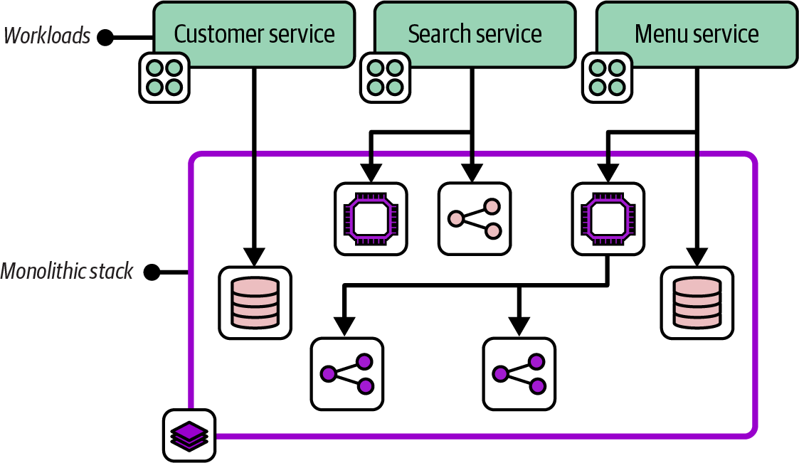
Figure 7-2. A monolithic stack with resources for a variety of workloads
A monolithic stack often includes infrastructure resources dedicated to different workloads, which is why it’s described as having low cohesion.
Motivation
People don’t set out to create a monolithic stack. As a system grows, adding infrastructure resources to an existing stack project is easier than creating a new project. A monolithic stack may start as a full system stack and expand to support new requirements. Or one stack within a system that uses a multiple stack pattern may grow over time to become unwieldy. A monolithic stack typically grows out of control organically.
Consequences
A stack with infrastructure resources used by different workloads, as opposed to those shared by workloads, creates high coupling among those workloads. A change to the infrastructure used by one workload risks affecting infrastructure used by other workloads.
A monolithic stack may cause different issues as it grows. Deploying changes to the stack takes longer. Longer deployment times make the process more difficult, including setting up and running tests and finding and fixing errors. These issues often manifest as poor performance on the four key metrics (see “The Four Key Metrics”), including not only the time to deliver changes to production and recover from failures, but also the frequency of changes as people tend to batch up changes in response to the effort needed.
The slower test-fix-test cycle caused by a larger stack size often leads to poor code quality, because people are less likely to prioritize smaller fixes and improvements. Making changes to a large stack is also riskier than changing a smaller one, with more content to break. The impact of a failed change may be broader since more services and applications are running on the stack.
Implementation
You build a monolithic stack by creating an infrastructure stack project and then continually adding code, rather than splitting it into multiple stack projects as it grows.
A team that finds itself with a monolithic stack should explore ways to split the stack into multiple stacks. Consider which design forces from Chapter 5 are relevant to find “seams” where it is natural to create subgroups. Look for other patterns in this chapter to refactor the monolithic stack into. Chapter 20 offers implementation guidance that can be useful to minimize service disruption when splitting a stack.
It could also make sense to convert a monolithic stack into an infrastructure composition, as defined in Chapter 6, if it’s useful to retain the relationships among the elements of the stack as it’s broken apart.
Related patterns
A Monolithic Stack pattern usually starts as a Full System Stack or an Application Group Stack.
Application Group Stack
An Application Group Stack pattern, depicted in Figure 7-3, defines all the infrastructure for a group of related applications and services in a single infrastructure deployment stack. Its workloads are usually related either because they provide a combined service or because they are owned by a single team.
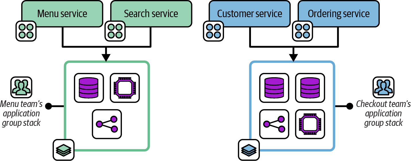
Figure 7-3. Two application group stacks
This diagram shows the workloads and infrastructure for two application teams from the FoodSpin example. The menu team develops the menu service for managing lists of food items as well as the search service for searching those items. The checkout team develops services for managing customer details and the food ordering process. Each team has a separate deployment stack that defines and manages the infrastructure for its services.
Motivation
When workloads share infrastructure, defining their infrastructure in one stack can make it easier to manage changes to them than defining them in separate stacks. The resources in each application stack may be more cohesive and closely integrated. When the infrastructure in a stack is used by a single development team, it may be easier to schedule changes than when it’s used by more than one team. Application group stacks are an example of following the “organizational structure” design force.
Application group stacks are sometimes useful as an incremental step from a monolithic stack to single service stacks or micro stacks.
Consequences
Managing all the infrastructure resources for a group of applications simplifies tooling, unless the stack has dependencies on other stacks, perhaps managed by other teams.
Designing deployment stacks around team ownership can make it difficult to move ownership of elements among teams. If FoodSpin decides to create a new application team to develop the search service shown in Figure 7-3, the menu team’s infrastructure stack will need to be split to avoid the conflicts that can come from two teams managing their infrastructure in the same stack.
Application group stacks may become too large, turning into monolithic stacks that are slow and unwieldy to manage.
Implementation
Define all the infrastructure used by a particular set of workloads in the stack project. The workloads may also use infrastructure shared with other groups of applications, like shared networking or higher-level policy controls.
Platform services may be application groups as well. For example, monitoring and log management services may be managed by a team or group of teams that manage their infrastructure in a shared stack.
Single Service Stack
A Single Service Stack pattern manages the infrastructure for each deployable application component in a separate infrastructure deployment stack.
Figure 7-4 shows three application services, each with its own infrastructure deployment stack.
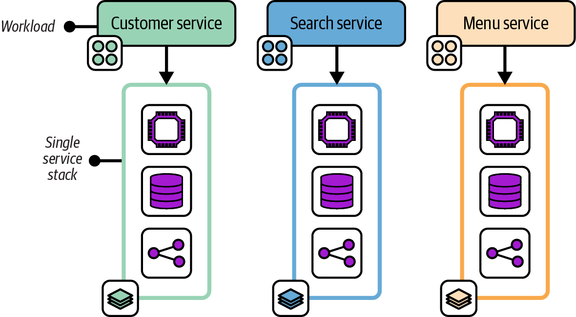
Figure 7-4. Three workloads, each with its own single service stack
Motivation
Single service stacks align the boundaries of the infrastructure deployment to the workload that runs on it. This alignment limits the blast radius for a change to one service, which simplifies the process of scheduling changes. A team can own the infrastructure that relates to its software.
Consequences
Having a separate infrastructure stack for each application can unnecessarily duplicate code. For example, each stack may include code to provision a database instance. There are several ways to mitigate this duplication in the implementation.
Implementation
The simplest Single Service Stack implementation involves creating and maintaining a separate infrastructure stack project for each application or platform service. This is appropriate when a workload’s infrastructure is not similar to the infrastructure for other workloads. When multiple applications use similar infrastructure, infrastructure code libraries can be used to reduce duplicated code.
In other cases, multiple applications or services have nearly identical infrastructure requirements. Rather than creating a separate infrastructure stack project for each application, a separate infrastructure stack instance can be deployed for each application using a single infrastructure project, following the Reusable Stack pattern described later in this chapter.
A single service stack does not necessarily include all the infrastructure used by a workload. Some infrastructure may be shared with other workloads, and so managed in a separate stack. What distinguishes a single service stack is that it includes all the infrastructure that is used only by a particular workload.
As with the shared service stack, a platform service can be considered an application. For example, a single service stack might include all the infrastructure used to run a monitoring application like Prometheus.
Related patterns
The Single Service Stack pattern falls between the Application Group Stack, which has multiple applications in a single deployable, and the Micro Stack, which breaks the infrastructure for a single application across multiple deployables. The pattern is often combined with the Shared Stack pattern.
Micro Stacks
The Micro Stack pattern divides the infrastructure for a single service across multiple infrastructure deployment stacks, as shown in Figure 7-5.
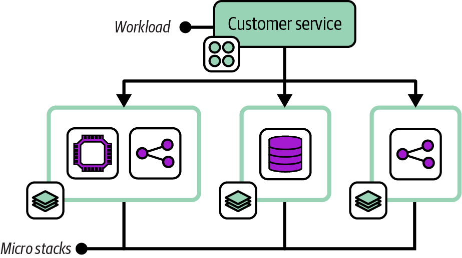
Figure 7-5. A workload with its infrastructure managed across three micro stacks
The infrastructure for one service is split into separate stacks for compute, storage, and networking. Note that a micro stack may define multiple resources. In this example, the compute stack includes a virtual server cluster and server-specific networking routes and firewall rules. The separate network micro stack includes load-balancer rules and routing from the public internet.
Motivation
Several design forces may lead to managing the parts of the infrastructure separately, including deployment and runtime concerns (as described in Chapter 5). The FoodSpin team might change the compute service for its customer management service fairly often, upgrading and patching the application server and OSs on the servers. Managing the database in the same stack means the team needs to take extra steps to manage the risk of losing data whenever it updates the stack. Splitting the database into its own stack simplifies changing the compute stack.
Consequences
Although a smaller deployment stack is simpler and easier to manage, creating multiple moving parts adds complexity to testing, delivery, integration, and management. Infrastructure code may be duplicated across multiple services.
Implementation
You can create and maintain separate Micro Stack projects for each stack used by a workload. If other workloads have similar infrastructure requirements, you may share a single stack project, using the same project to deploy a separate stack instance for each workload that needs it. For example, all the FoodSpin services use the same type of database with similar configurations, so a single database stack project can be used by each of the workloads.
Shared Stack
The Shared Stack pattern, depicted in Figure 7-6, provisions infrastructure for use by multiple workloads. It doesn’t include any infrastructure elements used by only one workload.
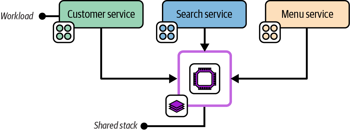
Figure 7-6. A shared service stack used by multiple workloads
A shared stack could, in theory, also be either a full system stack or an application group stack, but only if it has no infrastructure specific to any workload. In practice, most systems include multiple shared stacks as well as single service stacks or micro stacks.
The infrastructure resources in a shared stack are normally designed around a particular concern, such as global networking or a shared container cluster, as in Figure 7-6.
Motivation
Putting infrastructure resources that are shared by multiple workloads into a shared stack and those that are used by one workload into separate service stacks helps keep stacks cohesive and creates opportunities to define clean, loosely coupled integration points between them.
Applicability
Shared stacks are especially relevant for infrastructure that provides connectivity between workloads, such as networking and messaging; for infrastructure that provides platform services to workloads, such as monitoring; and for infrastructure that hosts multiple workloads, such as container clusters.
Consequences
Ownership of infrastructure projects and running instances should be carefully aligned with the teams that use it, to avoid the conflicts of sharing ownership.
Implementation
A shared stack is implemented as an infrastructure stack project, and provisioned as a running deployed stack for use by multiple teams to deploy applications to or to consume provided resources. Chapter 9 discusses techniques for exposing and integrating resources for Shared Stacks.
Stack Patterns for Multiple Instances of Infrastructure
We often need to deploy multiple instances of the same infrastructure, perhaps with some configuration differences. The most common example is environments for developing, testing, and running software. In other cases, we need to deploy multiple instances of the same infrastructure within an environment, such as database instances or application servers. We may also deploy multiple production replicas of a system across geographical regions, or dedicated instances for customers.
Chapter 12 discusses types of environments and design strategies in detail. However, deploying and maintaining multiple infrastructure instances is a foundational requirement. There are several approaches to implementing infrastructure deployment stacks to support this requirement. Two of the approaches described here, Multi-Environment Stacks and Snowflakes as Code, are antipatterns, common solutions that are usually harmful and should be avoided. The third approach, Reusable Stack, is a more generally useful solution.
The chapters following this one delve into the details of implementing and using reusable stacks, such as using configuration to manage differences between stack instances built from the same code and integrating multiple stacks. This section lays the groundwork for this, and indeed for the rest of this book.
Environments
Many of the examples in this book show three environments, usually development, test, and production. These are used purely to demonstrate the concepts of multiple environments, not as a suggestion that these are the environments you should use. Every organization has its own set of environments, often more than three, occasionally fewer, with its own naming scheme.
Chapter 12 describes patterns and strategies for designing and implementing environments, although it doesn’t recommend any particular set, either. Most of the chapters in Part III describe the progression of application and infrastructure code across environments. Those chapters also won’t tell you what to call them. That decision, I’m afraid, is up to your organization.
Multi-Environment Stack
The Multi-Environment Stack is an antipattern that defines and manages the infrastructure for multiple environments in a single-stack deployment, as in Figure 7-7.
For example, if there are three environments for development, testing, and production, a single infrastructure stack project includes the code for all three environments, and a single instance is deployed from this project.
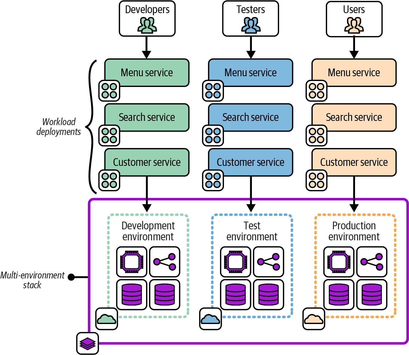
Figure 7-7. A multi-environment stack
Motivations
It feels natural to most people starting out with infrastructure code to create a single project for all their infrastructure.
Consequences
When running the stack deployment tool, the scope of a potential change is everything in the stack. If you have a mistake or conflict in your code, everything in the instance is vulnerable.4
When your production environment is in the same stack deployment as another environment, changing the other environment risks causing a production issue. A coding error, unexpected dependency, or even a bug in your tool can break production when you meant to change only a test environment.
Related patterns
Some people are tempted to turn to the Snowflakes as Code antipattern to move away from this antipattern. The Reusable Stack pattern is a better alternative.
Snowflakes as Code
The Snowflakes as Code antipattern, depicted in Figure 7-8, uses a separate stack source code project for each instance of infrastructure, even when the instances are intended to act as replicas of the same resources.
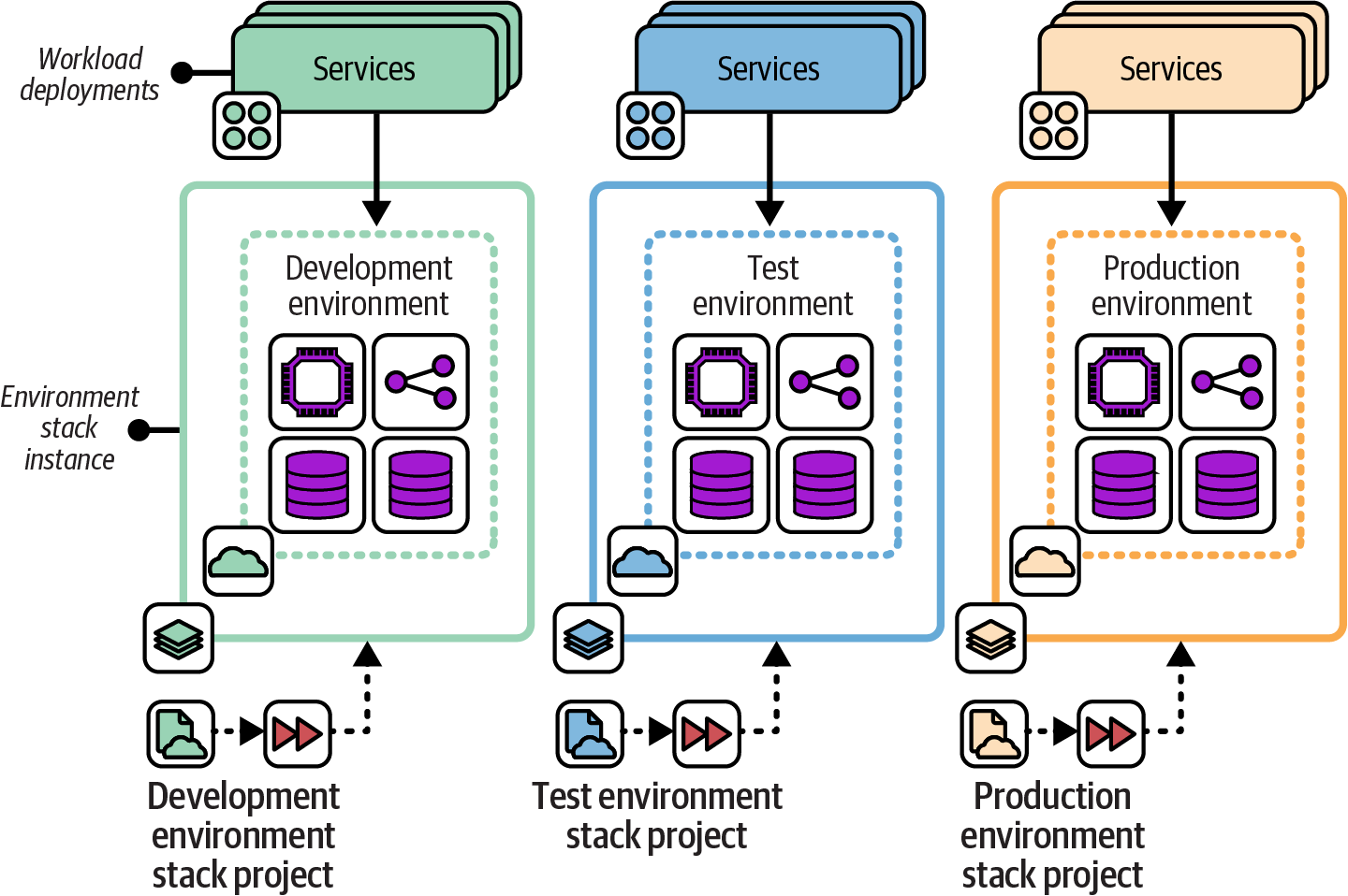
Figure 7-8. Snowflakes as Code use a separate copy of the stack project code for each instance
This example shows three environments, named development, test, and production, each with a separate infrastructure stack project. Changes are made by editing the code for one environment and then copying the changes into the projects for each of the other environments in turn.
Also known as
Snowflake Stack, Snowflake Environment.
Motivation
Snowflake stacks avoid the concerns of the Multi-Environment Stack antipattern by splitting each environment into a separate stack. Changes to one environment won’t affect another environment.
Snowflakes are often the fastest way to create a new environment, whether it’s a delivery environment or a new production environment (for example, for a new geographical region). It’s much easier to customize a new copy of infrastructure code without needing to worry about breaking the original environment.
Applicability
Snowflake code might be appropriate if you want to maintain and change instances of infrastructure that don’t need to be consistent. Arguably, this case isn’t Snowflakes as Code but simply separate infrastructure projects.
Consequences
Maintaining multiple copies of similar code quickly becomes unwieldy. So while this is a quick way to create a new environment, the cost of ownership per environment grows rapidly.
Making a change, improvement, fix, or update to all snowflake project code and environments is time-consuming. Changes made to one copy of the project may not work the same in others because of their differences. And inconsistencies have a way of growing over time. Some inconsistencies may be deliberate, such as different sizing of resources in production and test instances. But other inconsistencies creep in simply because there isn’t time to make a change or update everywhere. This is the original definition of the term “configuration drift.”
Related patterns
Environment branches (see “Distributing Code Branches as Artifacts”) may be considered a form of Snowflakes as Code. The Wrapper Stack pattern (see “Deployment Wrapper Stack”) is similar to Snowflakes as Code, but no infrastructure code is in the stack project. Each project contains only configuration for the instance of infrastructure.
Reusable Stack
In the Reusable Stack pattern, an infrastructure stack project is used to create multiple stack instances, as shown in Figure 7-9.
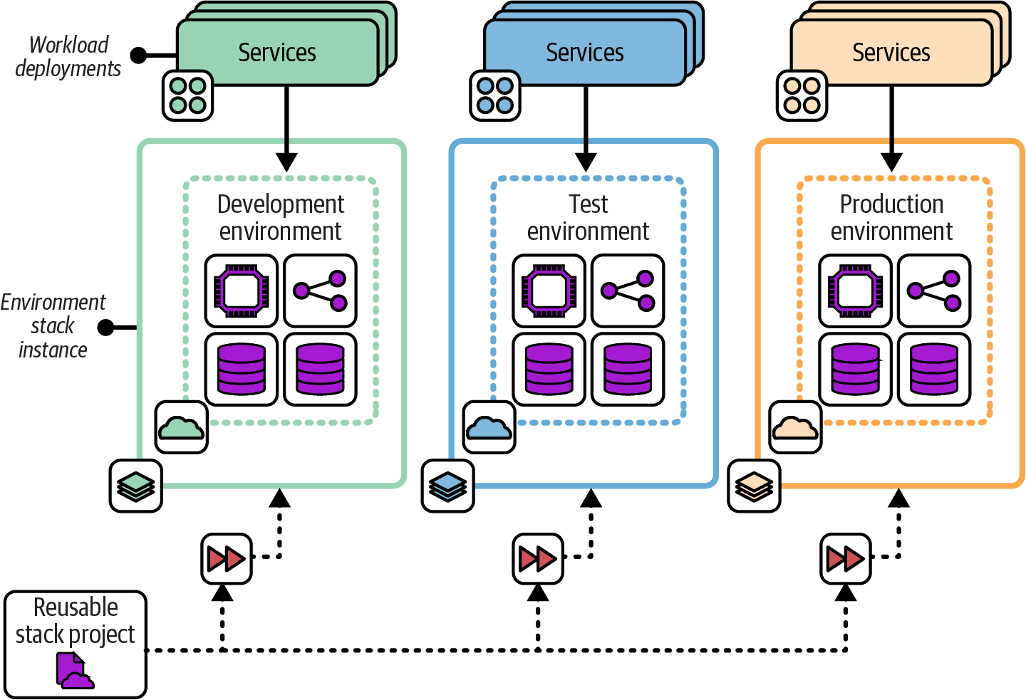
Figure 7-9. Multiple stack instances created from a single Reusable Stack project
Motivation
Using a single infrastructure stack project to create and update multiple instances makes it easy to keep those instances consistent. A change to the stack project can be applied to all the instances, ensuring they all have the latest updates, fixes, and improvements. The per instance cost of ownership is kept low, and the accumulation of technical debt and outdated versions of infrastructure is avoided.
Applicability
A reusable stack is useful when you need to run multiple instances of infrastructure elements that are essentially replicas. Software delivery environments (development, test, production, etc.) are a common example of this requirement. Stack projects can be reused to replicate production environments, such as deploying systems in multiple geographical regions.
Stacks can also be reused within an environment. Many of the patterns defined earlier in this chapter divide infrastructure into multiple stacks. When multiple workloads each need their own instance of a certain type of infrastructure, such as a database instance or load-balancing rules, a single stack project can be used to create separate instances.
Chapter 12 discusses approaches and patterns for designing environments that use reusable stacks.
The Reusable Stack pattern is less applicable when an instance needs to be heavily customized. However, many differences can be managed by making a reusable stack configurable, as explained in Chapter 8.
Consequences
Reusable stacks support many of the principles of cloud infrastructure described in Chapter 2, including making everything reproducible, avoiding snowflake systems, minimizing variation, and creating disposable components.
Quite often, stack deployments have varying requirements, such as sizing resources. The capacity required for production may be expensive to run for each development and test environment, for example. These differences can usually be managed by making the stack project configurable.
If changes to the stack project code are not deployed to all instances of the stack, the differences can grow to the point where applying the latest version of the stack code can be disruptive and risky. Changes should be tested and applied to all instances in a short time period, as described in the following implementation section of this pattern.
Implementation
A reusable stack is created as a single stack code project. This project code is then applied to create each new deployed instance of the stack and to apply updates to each instance.
Use the syntax of the stack tool to specify which instance you want to create or update. With Terraform and OpenTofu, for example, you specify a different state file or workspace for each instance. With CloudFormation, you pass a unique stack ID for each instance.
The following fictional stack command provisions two stack instances from a single project. The command takes an argument, env, that identifies unique instances:
> stack up env=development --source mystack/srcSUCCESS: stack 'development' created> stack up env=test --source mystack/srcSUCCESS: stack 'test' created
As a rule, you should use simple parameters to define differences between stack instances—strings, numbers, or in some cases, lists. Additionally, the infrastructure created by a reusable stack should not vary much across instances. Chapter 8 goes into much more detail on configuring instances of a reusable stack.
Changes to the stack project code should be applied to all existing deployed instances of the stack within a short time period, to avoid drift and ensure consistency. Infrastructure pipelines, described in Chapter 16, can be used to test changes to stack code before applying them to business-critical environments, just as you would do with software changes. Pipelines automate the process of quickly delivering changes to all instances.
Related patterns
The Reusable Stack pattern is an improvement on the Snowflakes as Code antipattern, making it easier to keep multiple deployments consistent.
The Wrapper Stack pattern (see “Deployment Wrapper Stack”) uses infrastructure code libraries to define the infrastructure code for a stack but uses a separate stack project to set parameter values for each deployment.
Conclusion
Infrastructure deployment stacks are fundamental building blocks for automated infrastructure. The patterns in this chapter are a starting point for thinking about organizing infrastructure into deployables. Next, Chapter 8 explains ways to manage configuration settings for multiple deployments of an infrastructure stack.
1 As defined in Chapter 4 of Building Evolutionary Architectures by Neal Ford et al. (O’Reilly).
2 See “Microservices” by James Lewis and Building Microservices by Sam Newman (O’Reilly).
3 See “The Art of Building Autonomous Teams” by John Ferguson Smart, among many other references.
4 Charity Majors shared her painful experiences of starting out with Terraform by building a multi-environment stack in her “Terraform, VPC, and Why You Want a tfstate File per Env” blog post.