Chapter 9. Integrating Infrastructure Stacks
As defined in Chapter 6, an infrastructure deployment stack is the smallest collection of infrastructure that can be changed independently. Chapter 7 described several design patterns that divide the infrastructure resources for an environment across multiple stacks, to make it easier and safer to change and update parts of the system. However, as discussed in Chapter 5, multiple stacks usually have dependencies among them. For example, if one stack creates shared networking structures like VPCs and subnets, another stack will need to provision its resources to use those networking structures.
This chapter describes several patterns for managing dependencies among infrastructure stacks. Many popular techniques can be used to implement discovery and integration of resources among stacks, but many of these techniques create tight coupling that makes changes more difficult. So coupling is a key factor in evaluating the patterns defined in this chapter and their applications to your infrastructure.
The first section of this chapter defines an example of a dependency relationship between two stacks. This example will be used to illustrate the patterns defined in this chapter. The second section describes several patterns for one stack to discover infrastructure resources that it depends on, which have been created in a different stack. The final section of the chapter discusses ways to implement resource discovery.
Example Infrastructure Deployment Stacks
The FoodSpin compute platform team provides development teams with a container cluster in each environment to run their applications. The compute team defines the cluster by using two deployment stack projects. The cluster_compute_stack defines the container cluster control plane and worker nodes, and the cluster_network_stack defines networking used by the cluster. This is an example of the Micro Stack pattern (“Micro Stacks”): the infrastructure for the workload (considering the container cluster itself to be the workload in this example) is split into two stacks rather than all defined in one stack.
Figure 9-1 shows these two stacks and the relationship between them.
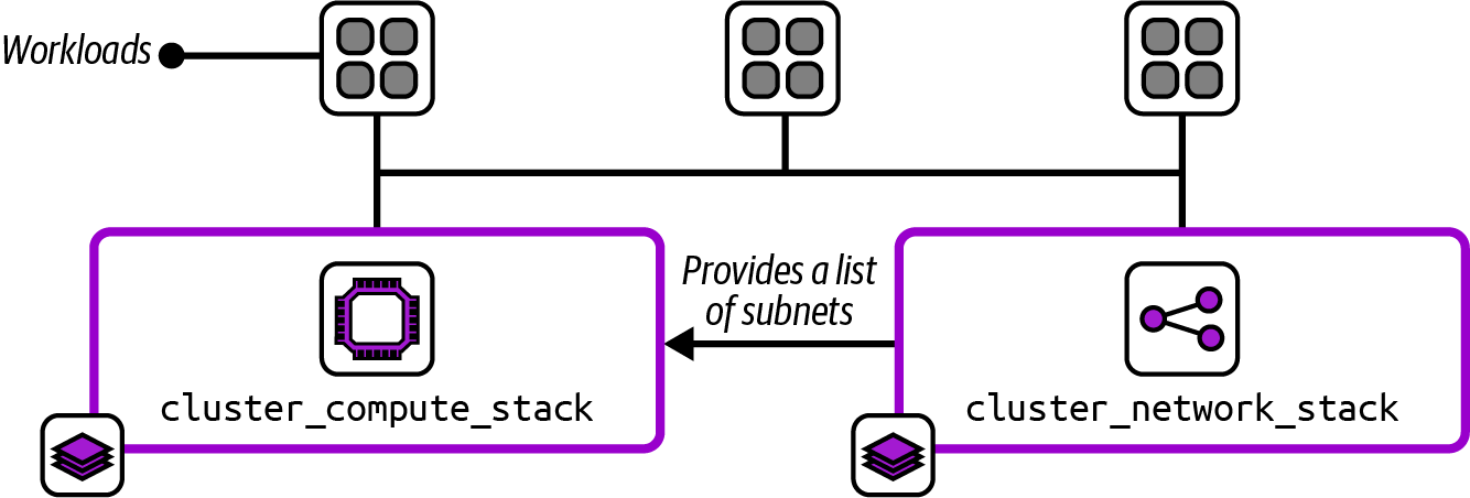
Figure 9-1. Two infrastructure stacks for implementing a container cluster and its networking
The network stack is the provider in this relationship, creating a list of subnets that are used by the compute stack, which is the consumer. The pseudocode for the network stack includes the declaration for the subnet resources:
subnets:count:3vpc:local.vpc_idname:cluster_subnet_${environment_name}_${count.index}address_range:get_address_subrange(vpc:local.vpc_id,how_many_subranges:3,which_subrange:${count.index})
It’s best not to get too hung up on the syntax of this example. The idea is that it defines three subnets, created within a VPC identified as local.vpc_id, which is defined somewhere else in the network stack project. The subnets will be named cluster_subnet_0, cluster_subnet_1, and cluster_subnet_2.
The pseudocode to define the container cluster includes a reference to the subnets to provision virtual servers for hosting the cluster:
container_cluster:name:compute_cluster_${environment_name}networking_subnets:-cluster_subnet_0-cluster_subnet_1-cluster_subnet_2
This example hardcodes the dependency between the two stacks, creating very tight coupling. Testing changes to the cluster stack code won’t be possible without an instance of the networking stack. If someone makes a change to the networking stack that involves changing the names of the subnets, they must know and remember to update the cluster stack as well. Otherwise, when they update deployed instances of the networking stack, their change will either fail or break the container cluster.
So instead of hardcoding dependencies, consider using one of the patterns described next for discovering dependencies.
Resource Discovery Patterns
The patterns in this section are used when two stacks have a dependency between them, a provider stack that manages an infrastructure resource and a consumer stack that needs to reference that resource. Each pattern describes a solution for discovering resources created outside the stack that depends on that resource. As the next section explains, these discovery patterns can be implemented in different ways, including in the consumer stack code, by an orchestration script, or in a composition definition. The examples in the following patterns show implementation within the consumer stack code.
The resource discovery patterns are as follows:
- Resource Matching
-
The consumer stack searches for the resources on the IaaS platform that match a naming or tagging scheme.
- Stack State Lookup
-
The consumer stack searches for the resources in the provider’s state data.
- Integration Registry Lookup
-
The provider publishes resource identifiers to a registry, and the consumer looks them up.
Let’s define each of these patterns in more detail.
Resource Matching
The Resource Matching pattern is used to discover a required resource by using the IaaS platform API to search for resources that match expected names, tags, or other identifying characteristics. In the following example, the cluster stack looks for subnets matching a naming pattern that includes the name of the environment:
container_cluster:name:compute_cluster_${environment_name}networking_subnets:cluster_subnet_${environment_name}_*
A value for environment_name is passed to the stack deployment tool as a configuration parameter, as described in Chapter 8.
This pattern assumes that the provider stack names its subnets according to this pattern, with a number at the end of each subnet name that can be discovered using the \* wildcard.
Motivation
Resource Matching is straightforward to implement with most stack deployment tools and languages. The pattern mostly eliminates hardcoded dependencies, reducing coupling.
Resource Matching also avoids coupling on tools. The provider infrastructure and consumer stacks could each be implemented using a different infrastructure code tool.
Applicability
Use Resource Matching for discovering dependencies when the people working on the consumer stack project can rely on the people working on the provider stack code to be consistent in the way they name and tag the resources they use as a dependency. When both stacks are owned by the same team, this is a bit easier, although mistakes can still happen. Consider switching to an alternative pattern if you experience issues with breaking dependencies across stacks owned by different teams.
Resource Matching is useful in larger organizations or across organizations, where different teams may use different tooling to manage their infrastructure but still need to integrate at the infrastructure level. Even if everyone uses the same infrastructure tool, Resource Matching reduces lock-in to that tool, creating the option to introduce new tools for different parts of the system.
Consequences
As soon as a consumer stack implements Resource Matching to discover a resource from another stack, the matching pattern becomes a contract. If someone changes the naming pattern of the subnet in the core networking stack, the consumer’s dependency breaks. The consumer can implement Resource Matching for any resource created by another stack, even if the people owning the other stack have no idea that these dependencies exist.
So a consumer stack’s team should discover dependencies only by matching resources in ways that the provider team explicitly supports. Provider teams should clearly communicate what Resource Matching patterns they support and be sure to maintain the integrity of those patterns as a contract.
Implementation
We have several ways to discover infrastructure resources by matching. The most straightforward method is to use variables in the name of the resource, as shown in the example code from earlier:
container_cluster:name:compute_cluster_${environment_name}networking_subnets:cluster_subnet_${environment_name}_*
The string cluster_subnet_${environment_name}_* will match the relevant VLAN for the environment.
Most stack languages have features to match attributes other than the resource name. Terraform and OpenTofu have data sources, and AWS CDK supports resource importing.
In this example, the provider assigns tags to its subnets:
subnets:count:3vpc:local.vpc_idname:cluster_subnet_${environment_name}_${count.index}tags:network_tier:compute_clusterenvironment:${environment_name}
The consumer code discovers the subnets it needs by using those tags:
lookup_resources:cluster_subnets:type:subnetmatch_tags:network_tier:compute_clusterenvironment:${environment_name}container_cluster:name:compute_cluster_${environment_name}networking_subnets:${cluster_subnets}
This pseudocode has a section to look up subnet resources that match two tags, network_tier: compute_cluster and environment, matching the environment parameter value. The pseudocode assigns the subnets it discovers to a variable called compute_cluster, which it refers to in the code to provision the container cluster.
Resource Matching can be implemented in stack code, as shown in the preceding examples, but can also be implemented in an orchestration script or composition definition and set using dependency injection, as explained in “Implementing Resource Discovery”.
Related patterns
The Resource Matching pattern is similar to the Stack State Lookup pattern. The main difference is that Resource Matching doesn’t depend on the implementation of the same stack deployment tool across provider and consumer stacks. On the other hand, Stack State Lookup is usually tied to values that are explicitly output by the creators of the provider stack, so it’s easier to manage those dependencies as a contract.
Stack State Lookup
A consumer stack uses Stack State Lookup to find provider resources by using state data maintained by the infrastructure deployment tool. Many stack management tools maintain data structures for each stack instance, as described in “Managing Infrastructure State”. This state data usually includes output values explicitly exported by the stack code. Examples include remote state files created by Terraform, OpenTofu, and Pulumi.
Also known as
Remote State File Lookup, Stack Reference Lookup, or Stack Resource Lookup.
Motivation
Stack management tool vendors make it easy to use their Stack State Lookup features to integrate various deployment stacks.
Most implementations of data sharing across stacks require the provider stack to explicitly declare which resources to publish for use by other stacks. Doing this discourages consumer stacks from creating dependencies on resources without the provider’s knowledge. This approach also makes the people maintaining the provider stack aware of which resources other stacks may depend on, so they can be careful when making changes to them.
Applicability
Using Stack State Lookup functionality to discover dependencies across stacks works when all the infrastructure in a system is managed using the same infrastructure deployment tool.
Consequences
Stack State Lookup tends to lock you into a single stack deployment tool. It’s possible to use the pattern with different tools, as described in the implementation of this pattern. But this adds complexity to your implementation.
This pattern sometimes breaks across different versions of the same stack tool. An upgrade to the tool may involve changing the stack data structures. This can cause problems when upgrading a provider stack to the newer version of the tool. Until you upgrade the consumer stack to the new version of the tool as well, the older version of the tool may not be able to extract the resource values from the upgraded provider stack. This stops you from rolling out stack tool upgrades incrementally across stacks, potentially forcing a disruptive coordinated upgrade across your estate.
Implementation
Terraform and OpenTofu store output values in a remote state file. Pulumi also stores resource details in a state file that can be referenced in a consumer stack by using a StackReference. CloudFormation can export and import stack output values across stacks, which AWS CDK can also access.1
In this pseudocode example, the networking stack exports the list of subnets it has created:
stack:deployment_name:cluster_network_stack_${environment_name}subnets:count:3vpc:local.vpc_idname:cluster_subnet_${environment_name}_${count.index}export:-cluster_subnet_list:cluster_subnet_*
The consumer stack then imports the subnets:
lookup_state_exports:stack_deployment:cluster_network_stack_${environment_name}set_variables_from_exports:cluster_subnets:cluster_subnet_listcontainer_cluster:name:compute_cluster_${environment_name}networking_subnets:${cluster_subnets}
In this example, the stack code implements the lookup from the remote state file. Implementing Stack State Lookup in stack code usually couples the dependency to the specific tool that deploys the provider stack. “Implementing Resource Discovery” describes alternative implementations to inject the dependency values as parameter values. Injecting parameter values avoids coupling to tools used by other stacks.
Integration Registry Lookup
To support Integration Registry Lookup, the provider stack publishes the values for resources it makes available to consumers in a shared key-value registry. The consumer looks up the resources in the registry to use them.
Also known as
Integration Registry.
Motivation
Using an integration registry makes dependencies among deployment stacks explicit. A consumer stack can use only values explicitly published by a provider stack, so the provider team can freely change the way they implement their resources.
A registry also decouples integration from the infrastructure tools. The consumer stack does not need to know what tool is used to deploy the provider stack, and vice versa. Each stack can be implemented with a different tool, which is useful in larger organizations that don’t have standardized tooling. This decoupling also makes it easier for teams to upgrade or migrate their tooling without impacting other teams.
Applicability
The Integration Registry Lookup pattern is useful for larger organizations, where different teams may use different technologies. It’s also useful for organizations concerned about lock-in to a tool.
If your system already uses a configuration registry (see “Implementing a Configuration Registry”) to provide configuration values to stack instances, following the Stack Parameter Registry pattern (see “Stack Parameter Registry”), it can make sense to use the same registry for integrating stacks.
Consequences
The configuration registry becomes a critical service when you adopt the Integration Registry Lookup pattern. You may not be able to provision or recover resources when the registry is unavailable.
Implementation
Many stack deployment tool languages support storing and retrieving values from various types of registries from within infrastructure code. For example, cluster_network_stack stores the identifiers of the subnets it creates in the registry:
subnets:count:3vpc:local.vpc_idname:cluster_subnet_${environment_name}_${count.index}export:-cluster_subnet_list:cluster_subnet_*registry:host:registry.foodspin.bizset_values:${environment_name}/cluster_subnet_list:${cluster_subnets}
The provider stores the subnet values in the location ${environment_name}/cluster_subnet_list. The consumer stack code retrieves the values from that location:
registry:host:registry.foodspin.bizget_values:cluster_subnets:${environment_name}/cluster_subnet listcontainer_cluster:name:compute_cluster_${environment_name}networking_subnets:${cluster_subnets}
The configuration registry is a prerequisite for using this pattern. See “Implementing a Configuration Registry” for a discussion of registries. Some infrastructure tool vendors provide registry servers, as mentioned in that discussion. With any registry product, be sure it’s well-supported by the tools you use and by those you might consider using in the future.
Implementing a more lightweight registry is also possible—for example, by storing output files in a shared location. However, changing values used for integration among stacks can be trickier than with normal stack configuration values. You may need to implement locking to prevent problems when a stack reads multiple input values while they are being changed by another stack’s deployment process.
Establishing a clear convention for naming parameters is essential, especially when using the registry to integrate infrastructure across multiple teams. Many organizations use a hierarchical namespace, similar to a directory or folder structure, even when the registry product implements a simple key-value mechanism. The structure typically includes components for architectural units (such as services, applications, or products), environments, geography, or teams.
For example, FoodSpin could use a hierarchical path based on the environment:
/infrastructure/├── development/│ └── cluster_subnet├── testing/│ └── cluster_subnet└── production/└── cluster_subnet
The subnets for the production environment are found at the location /infrastructure/production/cluster_subnet.
Related patterns
Like this pattern, the Stack State Lookup pattern stores and retrieves values from a central location. That pattern uses data structures specific to the stack management tool, whereas this pattern uses a general-purpose registry implementation. The Stack Parameter Registry pattern (see “Stack Parameter Registry”) is essentially the same as this pattern, in that a stack pulls values from a registry to use in a given stack instance. The only difference is that with this pattern, the value comes from another stack and is used explicitly to integrate infrastructure resources among stacks.
Implementing Resource Discovery
Infrastructure dependency relationships are usually defined when writing code; they’re resolved when the code is executed, during the deployment step of the infrastructure code processing lifecycle described in Chapter 4. Discovery of resources that a particular infrastructure stack depends on can be implemented within the stack’s code, or it can be implemented by an orchestration script or tool and then passed to the stack as a parameter. Key criteria for implementing integration among stacks includes avoiding tight coupling. Unfortunately, tight coupling is a common side effect of a popular approach to implementing resource discovery, which is in stack code.
Implementing Discovery in Stack Code
The integration patterns defined in this chapter describe various solutions for a consumer stack to discover resources defined outside the stack. Most infrastructure stack tools support directly implementing these patterns from within infrastructure code.
Consider this snippet from the earlier implementation example for the Resource Matching pattern:
lookup_resources:cluster_subnets:type:subnetmatch_tags:network_tier:compute_clusterenvironment:${environment_name}container_cluster:name:compute_cluster_${environment_name}networking_subnets:${cluster_subnets}
The essential part of this code is the container_cluster declaration. The rest of the snippet, everything in the lookup_resources declaration, contains details about storing and structuring parameter values. This code clutter isn’t directly relevant to the purpose of the stack.
But the deeper issue with implementing dependency discovery in the stack code is that it tightly couples the stack to the implementation of its dependency. The discovery implementation depends on the implementation of the provided resource, whether it’s the IaaS platform, stack tool state file, or configuration registry. The stack can be deployed only in the context of that implementation.
Chapter 7 described the benefits of breaking a monolithic stack into multiple, separately deployable stacks. Smaller, more cohesive stacks are easier and safer to change, and are quicker to deploy and test. The ability to deploy a stack in isolation enables the approaches described throughout Part III for separately developing, testing, and delivering each stack before integrating it into the larger system.
To deploy a stack in isolation, it should be possible to deploy a stack in different contexts, such as to a local emulator (where appropriate), to a lightweight test context without all the services of a full environment, or to an environment with a smaller subset of the full infrastructure estate.
When a stack has hardcoded discovery that depends not only on the resources provided by a stack it depends on, but on the way that stack is implemented and managed, then it’s difficult to deploy the stack in isolation. Tightly coupling the relationships among infrastructure stacks leads to a distributed monolith, a system that is divided into pieces that can only be developed, tested, distributed, and deployed together.
Moving resource discovery out of the stack code can decouple the implementation of discovery from the implementation of the stack, creating more flexibility for deploying it. This approach is dependency injection.
Using Dependency Injection
Dependency injection (DI) is an approach that decouples code from the implementation details of discovering its dependencies. The code component declares its dependencies as configuration parameters, and the deployment mechanism passes in the values for those parameters when provisioning the component. The implementation of dependency discovery is handled outside the stack, as I’ll discuss next.
The infrastructure stack code treats its dependencies like any other configuration parameters. For example, the container_cluster code would look like this:
parameters:-cluster_name-cluster_subnetscontainer_cluster:name:${cluster_name}networking_subnets:${cluster_subnets}
The code declares two parameters that must be set when applying the code to an instance. The cluster_subnets parameter is the dependency, set to a list of subnet identifiers that can be used to provision the container cluster. The cluster_name configuration parameter is a string assigned as the name of the cluster.
Origins of Dependency Injection
Dependency injection originated in the world of object-oriented software design in the early 2000s. Proponents of XP found that unit testing and TDD were much easier with software written for DI. Java frameworks like PicoContainer and the Spring Framework pioneered DI. Martin Fowler’s 2004 article “Inversion of Control Containers and the Dependency Injection Pattern” explains the rationale behind using the approach for object-oriented software design.
Managing Dependencies in a Deployment Script
As mentioned, dependency injection shifts the implementation of discovering dependencies out of the stack code. A common alternative place to implement discovery is in a stack deployment script (see “Infrastructure Deployment Scripts” for more). Consider a shell script as a simple example:
#!/usr/bin/env bashSUBNET_ID_LIST=$(stackvalue\--stack_instancecluster_network_stack_${ENVIRONMENT_NAME}\--export_namecluster_subnet_list)stackup\--stack_instancecontainer_cluster_${ENVIRONMENT_NAME}\--parametercluster_name=container_cluster_${ENVIRONMENT_NAME}\--parametercluster_subnets=${SUBNET_ID_LIST}
The fictional stack tool is used to fetch the subnet ID list from the state file of the cluster_network_stack_${ENVIRONMENT_NAME} stack deployment and set it as a shell script variable named SUBNET_ID_LIST. The script then runs the stack command a second time to provision the cluster stack instance, passing it two parameters, one with the name of the cluster, the other with the list of subnet IDs.
A stack deployment script can implement any of the resource discovery patterns described in this chapter. It can even implement different patterns for different contexts, such as when deploying the stack to a local emulator, or in a test suite where it may provide a stripped-down version of the needed resources. See “Use Test Fixtures to Handle Dependencies” for more on using test fixtures in place of dependencies.
It’s often a good idea to implement different stack deployment scripts, or a modular deployment script, to discover dependency and configuration values in different situations. Otherwise, stack deployment scripts can become complex spaghetti monsters that encode far too much detail of the stack implementations. “Using Delivery Orchestration Scripts” touches on how scripts for orchestrating delivery, build, and/or deployment of infrastructure stacks can grow out of control.
An alternative to a deployment script is using a composition to integrate stacks.
Wiring Stacks Together with a Composition
Chapter 6 described an infrastructure composition as a component that defines a collection of deployable infrastructure stacks. A composition could be viewed as replacing an imperative stack deployment script with a declarative configuration. This example defines the two stacks from the FoodSpin example used in this chapter as a YAML file:
composition:runtime_platformparameters:-environment_namestacks:-name:cluster_network_stackinputs:environment_name:${environment_name}outputs:-subnet_list-name:cluster_compute_stackinputs:environment_name:${composition.environment_name}cluster_subnet_list:${stack.cluster_network_stack.subnet_list}
The composition declares that the value for the subnet list output from cluster_network_stack will be passed as a parameter to cluster_compute_stack. The compute stack code doesn’t need to know where the subnet list comes from. A test stage for the compute stack could use a composition that gets the subnet list from a test fixture:
composition:isolated_test_for_cluster_compute_stackparameters:-environment_name:isolated_stack_teststacks:-name:network_test_fixture_stackoutputs:-subnet_list-name:cluster_compute_stackinputs:environment_name:${composition.environment_name}cluster_subnet_list:${stack.network_test_fixture_stack.subnet_list}
The network_test_fixture_stack is a smaller stack than cluster_network_stack used in other environments, so it’s faster to use for testing purposes.
Of course, using a composition definition to manage the integration among stacks requires a tool or service that reads the file and uses it to configure and deploy each stack.
Conclusion
Composing infrastructure from well-designed, well-sized stacks that are loosely coupled makes it easier, faster, and safer to make changes to your system. However, this approach requires a way to manage the discovery of dependencies that a stack depends on so the stack can be deployed. This chapter has given you useful ideas for managing dependency resource discovery, including selecting an appropriate resource discovery pattern such as Resource Matching, Stack State Lookup, or Integration Registry Lookup. I hope you’ll also see the benefit of using dependency injection to keep your stacks loosely coupled.
1 See the AWS CDK Developer Guide.