Chapter 12. Designing Environments
The concept of an environment is so pervasive in the IT industry that, paradoxically, it’s not well-defined. From an Infrastructure as Code viewpoint, an environment is a logical grouping of deployed infrastructure. Organizations may group their infrastructure into environments based on their own concerns. A common one is application instances that integrate to provide a service. In this case, you could have multiple production environments, each serving a different customer or region.
Some organizations group services into different environments even when they integrate with one another. For example, one environment might host a production customer-facing service, while another environment provides backend services like logistics or operational services like monitoring. Quite often, each environment has a common set of policies and access permissions, which is a driver for how to group their workloads and services.
Much of this chapter discusses design forces that apply to environments and that can be used to create and evolve your organization’s environment architecture.
Changes in technology, such as hardware virtualization and cloud native approaches to packaging and deploying software, are driving changes in the way people think about environments. Some people believe the concept of environments is obsolete. The truth is that infrastructure can be abstracted at various levels of the stack, but as with the other design forces discussed in this chapter, it’s important to consider the implications and draw the boundaries of abstraction at the right level for your situation. I will share a model for environment implementation layers that can help with this.
IaaS platforms provide structures for grouping resources as accounts (AWS), resource groups (Azure), and projects (Google Cloud). These structures have a lot in common with environments, so an environment architecture needs to consider what kind of relationship to create between IaaS resource groupings and environments.
An environment’s infrastructure should, of course, be implemented as code. Infrastructure stacks, as defined in Chapter 7, are deployable units of infrastructure code. So the chapter finishes by bringing environment architecture together with design patterns for infrastructure stacks to implement environments.
Although this chapter discusses delivery environments used to promote software and infrastructure changes through stages of testing, it leaves discussion of delivery processes for the next part of this book. In particular, Chapter 14 describes the lifecycle for delivering changes to infrastructure, and Chapter 16 explains using automated pipelines to test and deliver changes. While these are based on principles and practices from software delivery, neither this book nor this chapter offers guidance on structuring software delivery, or makes any recommendations on the environments you should have or how to use them.1
Multi-Environment Architectures
An environment provides infrastructure resources, platform services, and controls for running a set of workloads. In a simple situation, all of an organization’s workloads could run in a single environment. But more often, workloads need to be separated into more than one environment.
A multi-environment architecture has at least three categories:
-
Providing delivery environments for change management, such as software delivery
-
Splitting environments for manageability, such as ownership by different groups
-
Replicating and customizing environments for separate user bases, such as regions, customers (with dedicated single-tenancy environments), or brands or products
More-complex systems often find the need to split environments across more than one of these architecture categories. For example, if different product groups each have their own production environments, they probably also have separate delivery environments to test their software releases.
Multiple design forces are at play with each of these multi-environment architectures. Keep in mind that, as with any up-front system design, all you know for sure about the design decisions you make for your environments is that they will be wrong. Even if you get the design right at first, needs will change. Don’t assume that you will design your environments and be done with it. Instead, be sure to consider how you will make changes after the environments are in use. Changes may include splitting environments, merging them, and moving systems between them.
Multiple Delivery Environments
Most processes for managing changes to parts of a system—whether it’s software, infrastructure, or configuration—involve deploying a change into a series of separate environments before applying the change to a production environment. Developing and testing the change in a separate environment reduces the risk of causing a problem in a business-critical system. The environments used in the change delivery process are delivery environments. The process of validating and progressing a change through the stages of the delivery process is sometimes called the path to production.
Organizations and teams have their own groups and naming conventions for the environments in their path to production. Figure 12-1 shows a simple set of delivery environments that include one environment each for development, testing, and production, to use as a reference.
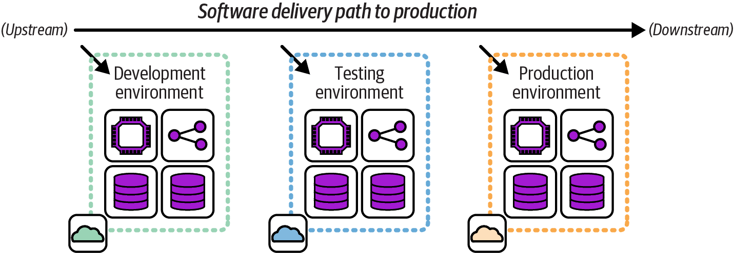
Figure 12-1. FoodSpin delivery environments
An upstream environment is used earlier in the delivery process. A downstream environment is used later in the process. In the FoodSpin example, the development environment is upstream of the testing environment, and the production environment is downstream of the development and testing environments. The metaphor is the change as a boat floating down a river.
Three key concerns for designing and implementing delivery concerns are segregation, consistency, and variation. These concerns are in tension with one another and need to be balanced:
- Segregation
-
Resources, services, and software in one environment should not affect other delivery environments. For example, testing a change to an application in an upstream environment should not be able to change data in a downstream environment, which could cause problems in production. Allowing a change in a downstream environment to affect an upstream environment can affect the outcomes of testing activities, making the delivery process unreliable. This concern suggests avoiding sharing infrastructure resources, such as a database cluster, across environments. However, as we’ll see later in this chapter, environments may be implemented as a higher layer over shared lower-level infrastructure.
- Consistency
-
Differences between resources or services across environments can also affect the validity of testing. Testing in one environment may not uncover problems that appear in another. Differences can also increase the effort and time needed to deploy and configure software in each environment and complicate troubleshooting. Lack of consistency across delivery environments is a major contributor to poor performance on the four key metrics, and resolving it is one of the leading drivers for the use of Infrastructure as Code.
- Variation
-
Some variation in delivery environments is usually necessary. For example, it may not be practical or necessary to provision testing environments with the same capacity as the production environment. Individuals may have different access privileges in different environments. At the very least, names and IDs may be different (appserver-development, appserver-testing, appserver-production).
As mentioned earlier, other multi-environment architectures may involve multiple production environments. When each production environment hosts different software or different parts of a system, a separate set of delivery environments is usually needed for each production environment, as shown in Figure 12-2.
In this example, FoodSpin has added a new service called SnackSpin. The software for SnackSpin is deployed to a separate set of environments than the core FoodSpin software because they are run as separate services.
In other cases, a single set of delivery environments may be used to test and deliver the same software to multiple production environments, as in Figure 12-3. This is a fan-out delivery pattern. As with other delivery environment patterns, this pattern mirrors a software delivery pipeline pattern.2
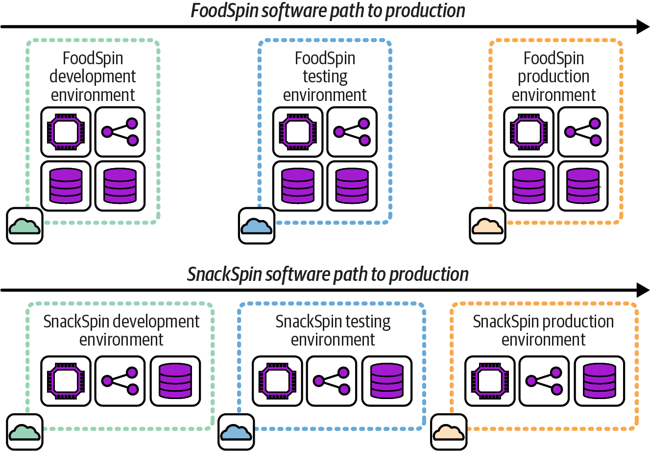
Figure 12-2. Separate delivery environments for separate workloads
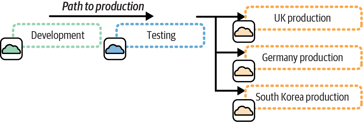
Figure 12-3. A single path to production fanned out to multiple production environments
The fan-out pattern works well when each production environment hosts an instance of essentially the same software, perhaps with some context-specific configuration. In this example, each production environment hosts an instance of the FoodSpin service for a different country, the United Kingdom, Germany, and South Korea.
Environments Split for Alignment
Running a very large system in a single environment may be unrealistic, especially if the workloads are not closely related, many stakeholders have conflicting requirements, or the governance requirements vary. In these cases, dividing the workload across multiple, separately configured environments can simplify design and maintenance.
As with any architectural decisions about where to draw boundaries between system components, it’s important to consider the design forces involved for environments, so you can keep cohesion high and coupling low. Environments should be aligned to specific concerns.
Aligning Environments to System Architecture
A defining characteristic of an environment is sharing infrastructure resources and platform services across multiple software deployables. But another word for sharing is coupling. As the number of things running in an environment grows, barriers to changing, upgrading, patching, or fixing the shared elements also grow. At some point, creating multiple environments may be useful, to reduce coupling across workloads.
In some cases, software systems have no dependencies between them, so the environments can be cleanly separated. This is an example of the shared-nothing architecture described in “Shared-Nothing Infrastructure Architectures”. In other cases, systems running in different environments need to integrate. Figure 12-4 shows an example of the first case.
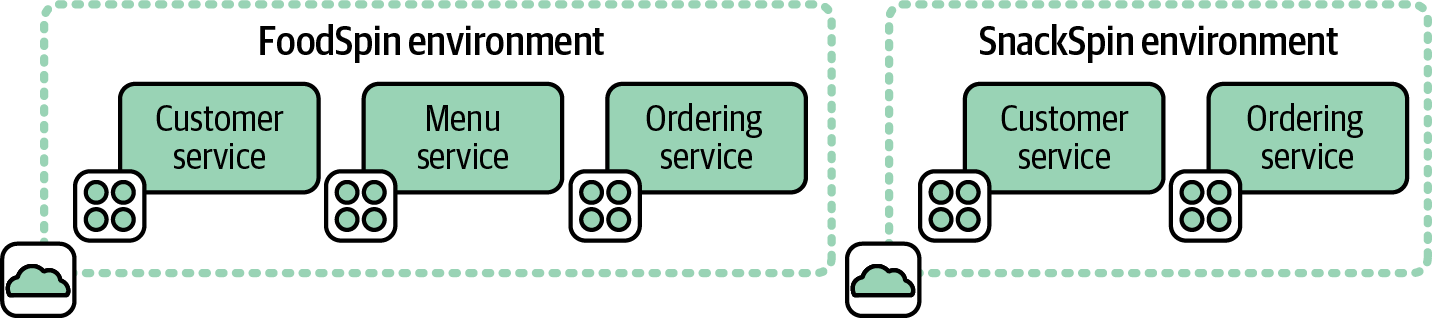
Figure 12-4. Environments for separate systems
FoodSpin runs two online stores: one for the core FoodSpin brand and another for the new SnackSpin brand built as a separate greenfield project. Each store has its own set of business capabilities and platform services, so there is no need to manage both in a single environment.
Figure 12-5 adds backend systems that handle data analysis and customer management for both the FoodSpin and SnackSpin online stores. These are hosted in a third environment.
Systems running in each of the storefront environments integrate with systems running in the backend services environment. Decisions about where to draw the boundaries between environments and which environment should host each service are driven, at least partly, by the system architecture.
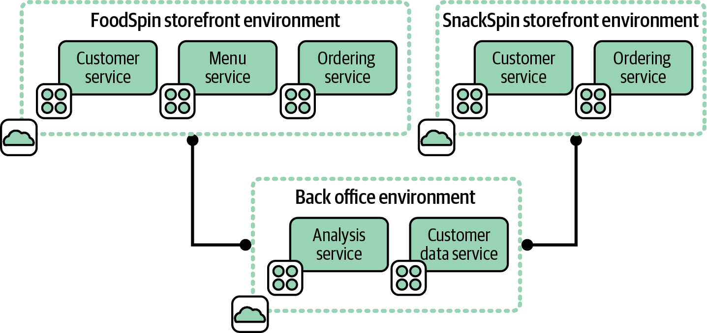
Figure 12-5. Separate environments for integrated systems
Each storefront environment is fairly cohesive, in that everything in it supports that particular storefront. If one environment hosted both storefronts, it would lack cohesion, since it would include services not used by both storefronts.3
Both storefronts in our example are coupled with the backend services. Hopefully, they are loosely coupled, meaning changes to a system on one side of the integration can usually be made without changing the other system.
Aligning Environments to Organizational Structure
Environments are often defined by who owns them, either in terms of who uses them or who provides and manages the infrastructure in them. For example, when FoodSpin created a new service called SnackSpin, the company decided to set up a new development and platform team to build it. The idea was that team members could develop the new service faster if they didn’t need to worry about disrupting the existing FoodSpin service’s systems. Each of the groups shown in Figure 12-6, FoodSpin core and SnackSpin, were able to develop, test, and deploy changes to their services independently of one another.
Each of the two environments is used and managed by a distinct set of teams.
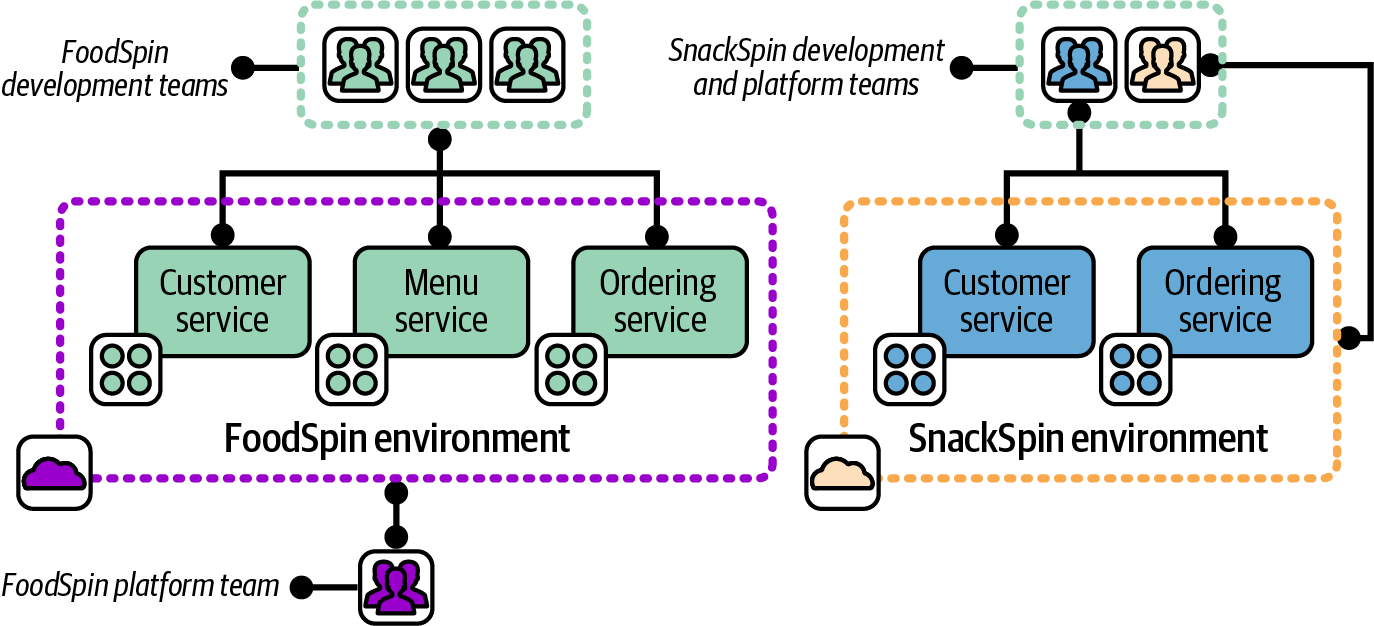
Figure 12-6. Two environments used and managed by separate teams
When the company decided to create shared analysis and customer management systems, as mentioned earlier, it set up a new development team for each of those services. The core FoodSpin platform team was asked to provide the hosting for the new system, which the team initially did by adding infrastructure to its existing environment, shown with the teams involved in Figure 12-7.
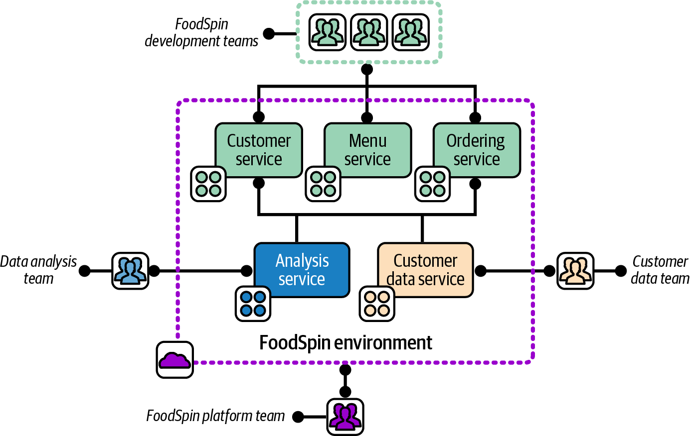
Figure 12-7. An environment aligned with the team that manages it
The FoodSpin environment is aligned with the platform team that manages it, but is shared by three development teams: the FoodSpin development team, the data analysis team, and the customer data team.
The architectural concerns described in the previous section led to the creation of a third environment to manage backend services, as shown earlier in Figure 12-5. This led to the discussion of whether to split out a third platform team to manage the new environment.
As mentioned in “Application Group Stack”, Conway’s law is an observation that organizational design tends to drive system architecture. Splitting out a new team to manage the infrastructure for SnackSpin would certainly have led to the creation of a separate environment, even if that hadn’t been already decided. Assigning a single team to provide infrastructure for two software development groups resulted, at least initially, in using a single infrastructure environment for both groups’ software.
Avoid Splitting Ownership of Delivery Environments
Some organizations separate the responsibility for maintaining development and testing environments from maintaining production environments. In more extreme cases, every environment in a multistage path to production may be managed by a separate team. Having a separate team managing each environment inevitably leads to different configurations and optimizations in each environment, which leads to inconsistent behavior and wasted effort.
The worst case of this I’ve seen involved seven environments for a path to production, each managed by a separate team.4 Deploying, configuring, and troubleshooting the software took nearly a week for each environment, which added nearly seven weeks to every software release.
Aligning Environments to Governance Concerns
Splitting a system across multiple environments can be useful to address governance concerns like compliance or security. Boundaries and integration points between environments are usually very clear, making it easy to enforce and audit the data and transactions that cross them. Infrastructure resources should not be shared across environments at a level that is material for governance, to reduce the risk of leaking data or authority.
Strong segregation by environment creates stronger governance and can also help reduce the impact of an attack. An attacker who gains access to an environment that hosts a user-facing application may have little access to backend systems with sensitive data. Hosting security operational services (such as monitoring, scanning, and log analysis), in a separate environment can prevent attackers from covering their tracks. Separately hosting systems with a broad scope of control, such as administrative and delivery pipeline services, can also limit the scope of damage an attacker can do.
With a well-designed system, governance and compliance aligns closely with architectural and organizational drivers.
Multiple Environment Replicas
As an organization scales, there is often a need to deploy multiple production instances of a system. Each environment is a replica, in that it hosts essentially the same software. However, each replica may have its own data set, such as a user base. There may also be requirements to configure the software and the infrastructure in different ways for different replicas. So, as with delivery environments, the need for consistency (which helps keep maintenance costs low), variation (to customize for different use cases), and segregation are usually in tension with one another.
Three common reasons for deploying replica environments are operability scenarios (such as resilience), geographic distribution, and multiple user bases. These reasons may be combined. For example, a common resilience scenario is running replicas of environments in multiple regions. The reasons may also be combined with other multi-environment architectures. System replicas in different geographical areas may be subject to different legal regulations, which can drive alignment to governance concerns as discussed previously.
Designing Environments for Operability Scenarios
Replicating environments can be useful to support operability scenarios, particularly for availability and scaling. Both types of scenarios involve running multiple environments, each of which can handle any given workload interchangeably.
Availability scenarios address situations where one environment is impaired. For example, if services in one data center or cloud-hosting region have an issue, traffic can be rerouted to a replica environment hosted in another data center or region. Availability scenarios can also be handled with a single environment that spans multiple hosting zones. However, a replica environment is often a convenient unit for providing redundancy, since it should include all the resources and services needed to continue handling workloads independently.
Environment replicas can be used for scalability scenarios using approaches very similar to those used for availability, and may even use the same implementation. When the active workload nears the maximum capacity for an environment, one of the potential strategies is to provision an additional replica environment and redirect a portion of traffic or work to it.
Some organizations run multiple environment replicas continuously, shifting their loads to gracefully handle failures or local surges in traffic.
Availability and capacity can be handled at other levels of the system than the environment. Compute capacity may be automatically scaled, data replicated, and workloads shifted across parts of a system within one environment. Environment-level replication can be useful as one part of a multitiered approach to these scenarios.
Distributing Environments Geographically
Organizations can use various approaches for structuring their systems, infrastructure, and environments to serve users in different geographical regions.
One concern when deciding on the right approach is latency. Even when running on a public cloud service, your system will be hosted in a physical data center that may be far enough from some of your users, in terms of network connectivity, that latency may affect their experience. Replicating or distributing some parts of your system so they are hosted closer to your users can address this.
Figure 12-8 illustrates an option for FoodSpin that uses a single environment to centrally serve customers in the UK, Germany, and South Korea.
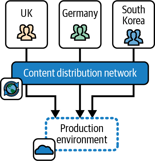
Figure 12-8. A single environment for multiple regions
FoodSpin can use a CDN to cache static assets like web pages, client-side scripts (JavaScript), and images closer to users. Some executable code could also be distributed using edge computing offered by a CDN provider. And even if a system’s implementation doesn’t lend itself to easily using these types of services, parts of the system could be explicitly deployed to data centers or cloud-hosting locations closer to users. There is a natural tendency to think of an environment as being located in a single region, but you can choose to draw its boundaries across regions if it’s useful.
But many organizations prefer to define a separate environment for each region to support customizations for local markets or businesses. For example, FoodSpin may have a payment partner in South Korea, which means FoodSpin doesn’t need to deploy the part of its system used for payments in the UK and Germany. Other parts of the service may need to be customized to integrate with the local partner. So FoodSpin needs to deploy different builds of its software in different regions, leading the company to run a separate environment for each region, as shown in Figure 12-9.
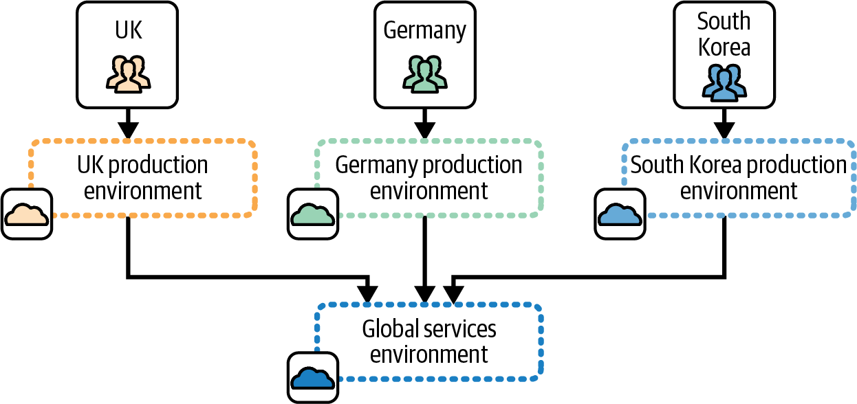
Figure 12-9. A separate environment for each region
In this example, FoodSpin also runs a separate environment for centralized services, including data analytics and customer management.
Customizing the software for each region complicates the testing needed, which in turn complicates the path to production for the software. If the customization is implemented so a single build of the software can be used, and simply configured separately for each environment, the teams may be able to use a fan-out path to production, as shown earlier in Figure 12-3. The fan-out pattern minimizes the effort and expense of maintaining multiple regions.
If the software is heavily customized, however, the teams will need separate paths to production for each environment, each with a separate set of delivery environments, as in Figure 12-2.
Often different regions fall under different legal regulations. FoodSpin may need to meet different requirements in the UK, Germany (as part of the EU), and South Korea, which could lead to differences in the way infrastructure is implemented. It’s often feasible to implement systems so that a single build of the software and even the infrastructure meets the regulations of each region it’s used in. However, the regulations may still require separate hosting. For example, data residency laws control where personal data for users can be transferred or stored. This leads back to governance concerns as a driver for designing environment boundaries.
It’s often theoretically possible to adhere to local regulations, including data residency, within a single environment with careful system design. But environments offer clear boundaries, reducing the risk of a misconfiguration or other mistake that breaks regulations. The boundaries of an environment can also simplify auditing.
Replicating Environments for User Bases
A common business model provides a service customized for different markets, customers, or partners. Some are white-label services, where the provider hosts the service for different customer companies, customizing the system for each customer’s brand so the customer can market it as their own. Online service white labeling is used in telecommunications, finance, retail, and many other domains.
Each white-labeled or partnered system may have customized branding or features. Each will usually have separately managed data, such as products and users. A person who uses the FoodSpin menu service will use a separate login for each, and will not expect to see their dining history from one restaurant appear on the menu service for another one.
The simplest way to use the same software to implement separate brands is to deploy a separate instance of the software for each. An alternative is to implement a multi-tenant system, where a single hosted instance serves multiple brands. Customized branding, features, and user data separation is implemented in the software.
Multitenancy makes more efficient use of infrastructure resources and takes less work to maintain. However, it requires more sophisticated software development. Also, some governance concerns, such as data residency, may require separate single-tenant systems, where each instance serves only one brand. Some organizations choose to host each single-tenant system in a separate environment. The implications of this approach are similar to those described for aligning environments to geography. The cost and effort to update, run, and maintain multiple system instances can be difficult to control.
Environment Implementation Layers
Virtualization and cloud technologies have increasingly moved the level of abstraction between application software and the hardware it runs on. IaaS uses virtualization to separate concepts like servers, disks, and load balancers from their hardware implementations. PaaS takes another step, discarding abstractions that imitate hardware devices, and instead using abstractions aligned with application architecture. A container wraps a compute process and the smallest subset of the OS it needs to run. Serverless strips the abstraction even further to the execution of a single operation.
The implementation of an environment is evolving with the layers of infrastructure abstraction. Figure 12-10 shows the progression from physical environments to environments running on shared runtimes such as container clusters.
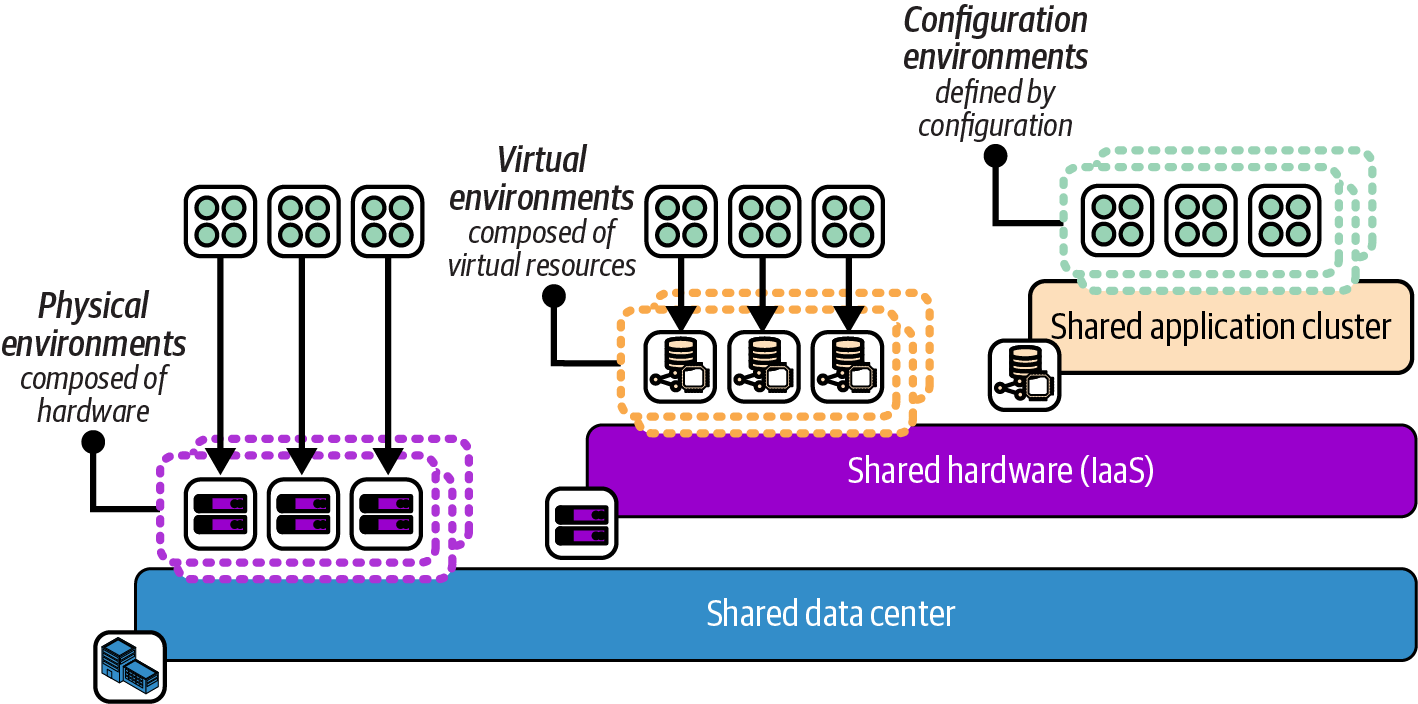
Figure 12-10. Increasing levels of abstraction layers for environments
A physical environment has dedicated hardware and shares infrastructure only at the level of the data center, such as networking and power.
Virtual environments share hardware using an IaaS cloud. You provision dedicated application runtime resources for each environment, such as a container cluster or virtual servers. But the underlying physical hardware is abstracted or even shared, with no distinction between hardware for different environments.5
A configuration environment is an application-level construct. Applications are deployed onto a shared application runtime service, such as a container cluster. Environments are defined by configuration (for example, using namespaces).
Using Design Forces to Choose the Environment Implementation Layer
The level of abstraction you can use to design your environments is constrained by the type of application. Normally, only cloud native applications implemented as serverless code or containers can be hosted in a configuration environment, unless you implement custom mechanisms for cohosting instances for different environments on shared virtual servers.
However, even if you are technically able to deploy application instances on shared infrastructure, it’s important to consider the level of isolation you need between environments, and what you can achieve with the technology. Many of the design forces discussed earlier in this chapter that lead to separating environments may not be satisfied when the environments are implemented on a shared runtime service. Here are some examples:
-
A highly regulated system may require that test code that hasn’t been approved for production must be prevented from accessing production data by stronger segregation than a deployment configuration setting.
-
A runtime system may need to be optimized for multiple types of workloads. For example, one workload may need to handle high volumes of transactions with low latency, while another may load and analyze large data sets. These conflicting requirements may need separate environments defined at a lower level of abstraction than namespaces in a container cluster.
-
Upgrading or even patching a runtime system may require downtime, or at the least, risk disrupting workloads running on it. The more environments running on the system, the broader the blast radius for planned or unplanned disruption. The number of teams and stakeholders who need to be involved in scheduling upgrades can add friction to the process. This friction can lead to upgrading and patching less often, which then leads to running outdated software, perhaps even versions with exploitable vulnerabilities.
-
Even when a runtime system has automated recovery features, some availability scenarios can be managed only by running multiple instances that share less of the underlying infrastructure. A failover between two zones of a container cluster doesn’t help when cluster management services fail.
Testing and Delivering Changes to Environment Infrastructure
Your environments are defined at a certain level of abstraction on top of a shared layer of infrastructure. Systems need to be tested at each layer of abstraction. Chapters 14 through 18 discuss progressively testing infrastructure, but for now, Figure 12-11 shows how environment abstraction layers are progressively tested from the bottom up.
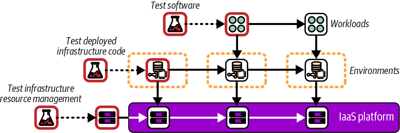
Figure 12-11. Testing infrastructure abstraction layers
The bottom layer is the IaaS platform. Whoever is responsible for that layer, whether it’s a cloud vendor or an in-house team, needs to test the configuration of physical systems, including operating systems, hypervisors, and network device configuration. They also need to test that resources are made available correctly via the IaaS API. Testing of changes to the underlying IaaS platform and physical-level systems is done without disrupting its users. Very few IaaS cloud customers are aware of changes at this level, other than reading announcements when new types of resources have been made available for use.
The next layer above the IaaS is the layer of most relevance to readers of this book: testing the environments and services made available by using code to deploy infrastructure. Figure 12-11 shows the first environment being tested without applications running in it. Having a separate environment for testing infrastructure code avoids interfering with software development and testing activities by deploying untested infrastructure code to software delivery environments.
IaaS Resource Groups and Environments
Each IaaS platform provides a base-level organizational structure for resources. With AWS, this is accounts; Azure has resource groups; and for Google Cloud it’s projects. For lack of a common term, I’ll call these IaaS resource groups. The vendors provide other groupings for managing hierarchies of resource groups, such as organizations in AWS and Google Cloud, and management groups in Azure.
An IaaS resource group is the default level for defining permissions, allocating costs, and other fundamental configuration that applies to all the resources allocated within it. A key question for an environment architecture when using IaaS is how to align resource structures and environments.
A common, basic approach is to create multiple environments in a single IaaS resource group. Resource groups can be difficult to create and configure. Many organizations put heavyweight governance around the creation of AWS accounts, Google Cloud projects, and the like, so teams find it easier to create a new environment inside an existing group than to have a new group created.
The drawback of having multiple environments in one resource group is that it results in sharing at least some configuration, access policies, and resources across those environments. It’s usually possible to segregate resources and configuration within a resource group, to at least some extent—for example, by adding a filter to apply a policy to subsets of resources based on identifiers or tags.
However, it’s easier and more reliable to segregate resources and configurations between IaaS resource groups than within them. So another approach is to create a separate resource group for each environment. This approach can be taken further, splitting parts of a single environment across more than one resource group. These structures may be divided following similar design forces as those described for environments.
Figure 12-12 shows how FoodSpin uses three AWS accounts to create a single environment.
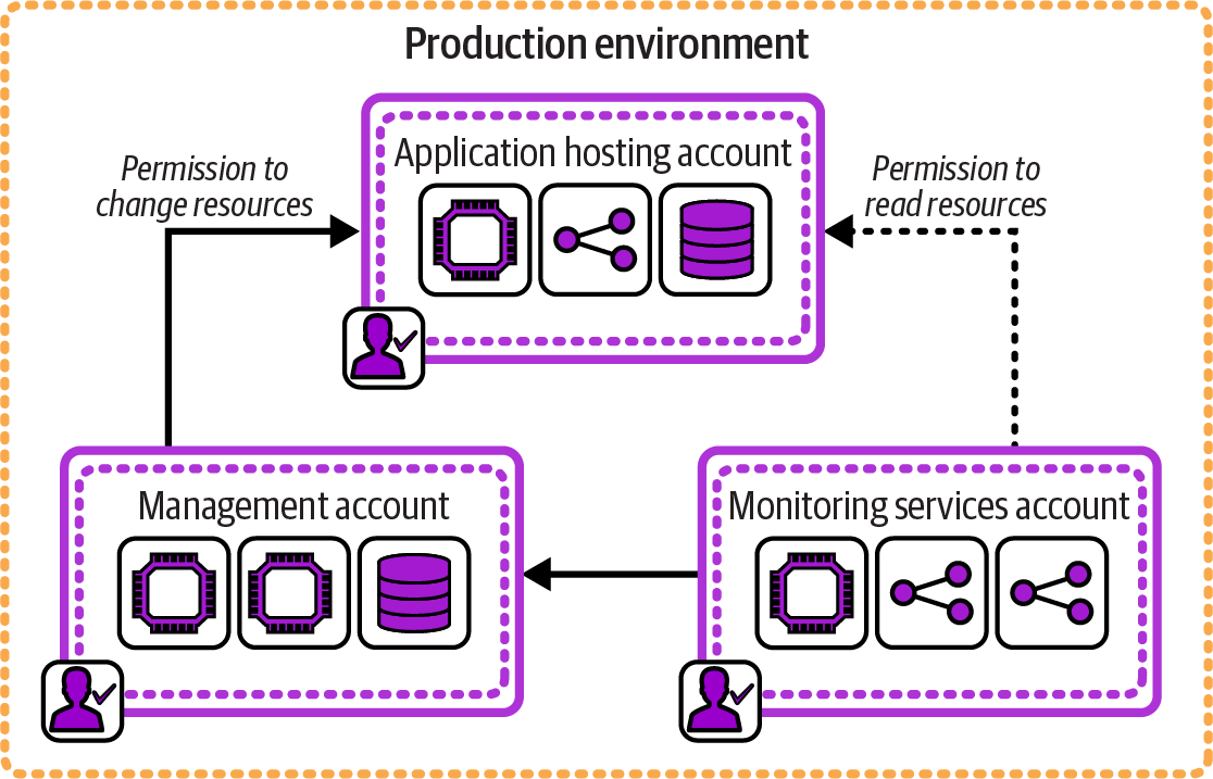
Figure 12-12. One environment composed of multiple IaaS resource groups
One account hosts the application software that directly serves users. A separate management account runs services with administration permissions to make changes to the application account, such as an infrastructure management pipeline. A third account runs monitoring services, receiving logs from the applications account and making read-only requests to examine resources running in that account. The application-hosting account has no access to the other two accounts. These three accounts have clearly separated and limited permissions according to the needs of the workloads within each.
IaaS resource groups are designed as a boundary for configuration, permissions, and accounting. So using one or more resource groups for each environment makes for more natural alignments of governance, operability, and other design forces for environments. Many organizations find it useful to align resource groups to ownership by team. Permissions for each AWS account, Azure resource group, or Google Cloud project are assigned to one group of people rather than giving each team permissions for resources owned by other teams in a shared group.
Going one step further, maintaining a separate IaaS resource group for each application or service not only aligns the permissions and configuration with current team ownership but also simplifies alignment when team ownership changes. As we know, system designs will change, including ownership of parts of a system by different teams. It’s easier to reassign the permissions for a resource group from one team to another than to move the infrastructure and configuration from one team’s resource group to another’s. The lowest level of granularity for ownership of infrastructure content is typically the application or service, so aligning IaaS resource groups at this level creates the most flexibility for managing changes.
As I mentioned earlier, people commonly put multiple environments in a single AWS account, Azure resource group, Google Cloud project, or equivalent because creating and managing new IaaS resource groups is difficult. An architecture that aligns resource groups at a lower level of granularity, even per environment, means you will be creating and managing many more of them. Therefore, a prerequisite of fine-grained resource groups is defining and managing them as code so they can be easily created, updated, and kept consistent. Managing IaaS resource groups as code gives all the benefits of defining anything as code, including auditability and hooks for automated governance.
Environments with Multiple Stacks
The Reusable Stack pattern (“Reusable Stack”) describes an approach for implementing multiple replica environments. This pattern is straightforward to implement when your environment is defined as a single stack.
However, Chapter 7 also describes patterns for breaking a system across multiple stacks (“Patterns for Sizing and Structuring Stacks”). As a system grows, using a single stack for each environment becomes unwieldy, becoming a Monolithic Stack.
When a system that is replicated in multiple environments is broken into multiple stacks, each stack will need to be replicated in each environment. Figure 12-13 shows the example delivery environments, each of which hosts the set of stacks described in the example for the Single Service Stack pattern (“Single Service Stack”).
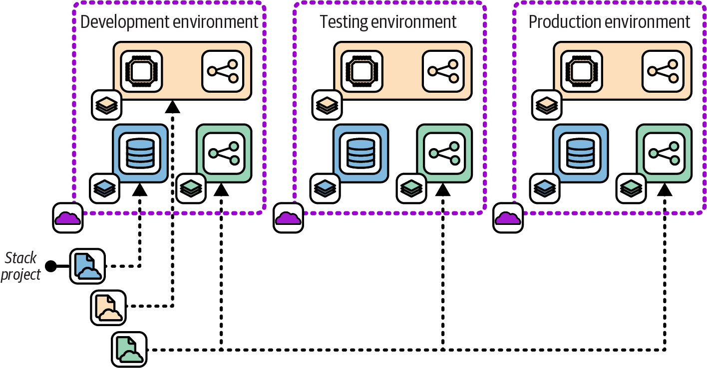
Figure 12-13. Using multiple stacks to build each environment
Each of the three service stacks—browse, search, and administration—is defined as a stack code project. To create an environment, the stack tool is run to deploy each of the three stacks. To create a new environment called demo using the fictional stack tool, the FoodSpin team would run the command three times:
$stackupenv=demo--sourcebrowse_stack/srcSUCCESS: stack 'browse-demo' created$stackupenv=demo--sourcesearch_stack/srcSUCCESS: stack 'search-demo' created$stackupenv=demo--sourceadmin_stack/srcSUCCESS: stack 'admin-demo' created
When the code in one of the stack projects changes, the updated version of the stack project needs to be deployed in each environment, but the other stacks aren’t touched. Chapter 5 describes strategies for splitting systems into multiple components, and Chapter 9 discusses how to integrate infrastructure across stacks.
Chapters 14 through 20 go into more detail of how multiple infrastructure components can be developed, tested, and delivered.
Conclusion
Environment architecture is a topic that is often taken for granted. Many IT organizations suffer from design decisions they have made not from conscious thought, but from habits and assumptions about what is “industry best practice.”6 This chapter describes aspects of designing and implementing a conscious architecture for environments. Infrastructure as Code creates an opportunity to move beyond heavyweight, static environments. Environments should be evolvable, as with every part of a system, so they can be continually adapted and improved with changing needs and better understanding.
1 Readers interested in these topics may find Continuous Delivery by Humble and Farley (Addison-Wesley), Continuous Delivery Pipelines by Dave Farley (independently published), and Continuous Deployment, by Valentina Servile (O’Reilly) useful.
2 Read more about fan-out and fan-in pipelines for software delivery in the article “Modeling Deployment Pipelines: Build Propagation Using Fan-In/Fan-Out” by Aravind S.V.
3 The two storefronts could share services. The FoodSpin team has had many debates about whether and how to consolidate its services, but the business priority was to accelerate the development of SnackSpin without disrupting the existing FoodSpin business, which led to separate implementations.
4 The environments were development, QA, systems integration testing (SIT), user acceptance testing (UAT), operations acceptance testing (OAT), pre-prod, and production.
5 In practice, your cloud vendor may give you options to override the abstraction—for example, by specifying that particular resources should not share physical hardware with one another.
6 I mentioned in the preface why I’m not a fan of the term “best practice.”