Chapter 14. Building Clusters as Code
Chapter 3 described an application hosting cluster as a service that dynamically deploys and runs application instances across a pool of servers (see “Compute Resources”). Examples of application cluster systems include Kubernetes, AWS ECS, HashiCorp Nomad, Mesos, and Pivotal Diego. This model separates the concerns of orchestrating applications from the concerns of provisioning and configuring the servers they run on (see Figure 14-1).
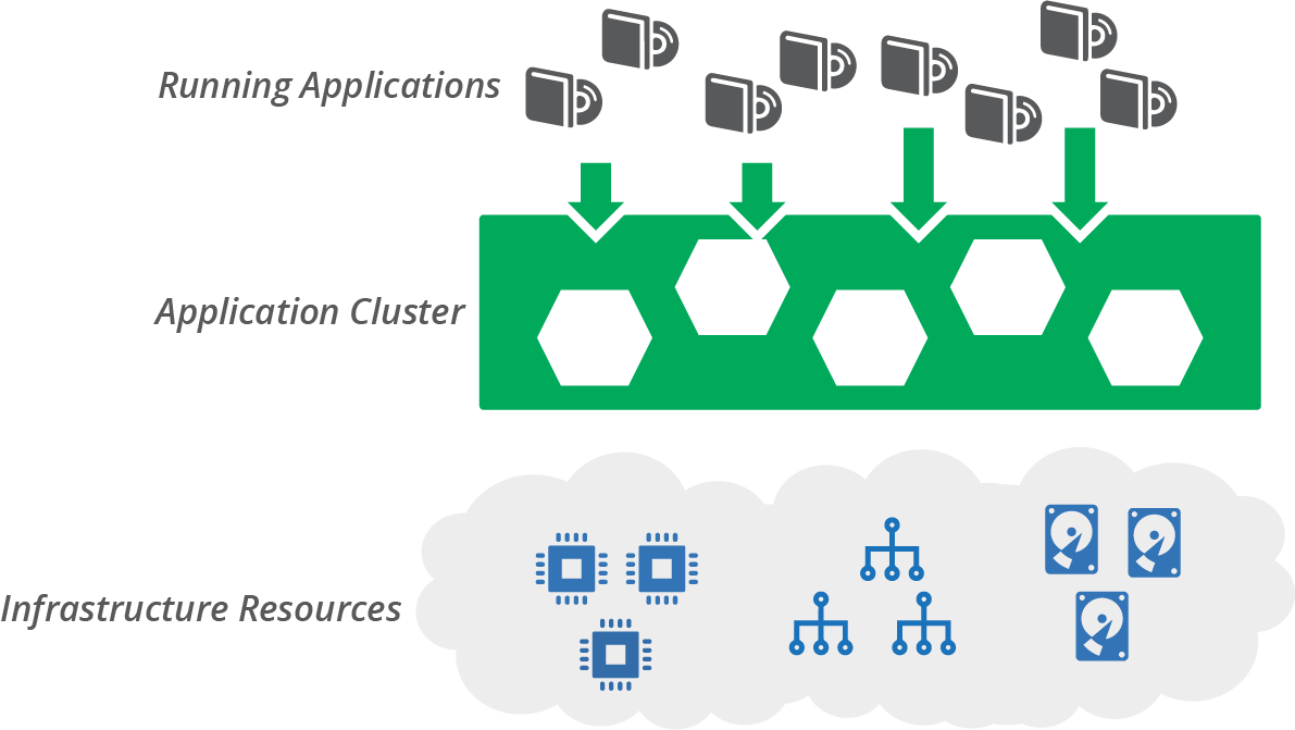
Figure 14-1. An application cluster creates a layer between infrastructure resources and the applications running on them
You should, of course, use code to define and manage your application cluster. As explained in Chapter 10, you can build an application cluster as one or more application stacks as code. In this chapter, I give some examples of what this can look like. I show some different stack topologies, including a single stack for a whole cluster, and breaking clusters across multiple stacks (see “Stack Topologies for Application Clusters”). I include diagrams for pipelines to deliver infrastructure code changes for these topologies.
I also discuss strategies for sharing clusters, or not sharing them, across environments and teams (see “Sharing Strategies for Application Clusters”). I close the chapter with a discussion of infrastructure for serverless applications (see “Infrastructure for FaaS Serverless”).
Application Cluster Solutions
There are two main approaches for implementing and maintaining an application cluster. One is to use a managed cluster as a service, usually provided as part of your infrastructure platform. The other is to deploy a packaged cluster solution onto lower-level infrastructure resources.
Cluster as a Service
Most infrastructure platforms provide a managed cluster service. You can define, provision, and change a cluster as code using your stack configuration tool. Using a cluster as a service is a matter of creating a stack that includes the cluster and supporting elements.
Many of these clusters are based on Kubernetes, including EKS, AKS, and GKE. Others are based on a proprietary container service, such as ECS.
Managed Kubernetes Clusters Are Not a Cloud Abstraction Layer
At first glance, vendor-managed Kubernetes clusters appear to be a great solution for developing and running applications transparently across different cloud platforms. Now you can build applications for Kubernetes and run them on whatever cloud you like!
In practice, although an application cluster might be useful as one part of your application runtime layer, much more work is required to create a full runtime platform. And achieving true abstraction from the underlying cloud platforms is not trivial.
Applications need access to other resources than the compute provided by a cluster, including storage and networking. These resources will be provided differently by different platforms, unless you build a solution to abstract those.
You also need to provide services such as monitoring, identity management, and secrets management. Again, you will either use a different service on each cloud platform, or build a service or abstraction layer that you can deploy and maintain on each cloud.
So the application cluster is actually a small piece of your overall application hosting platform. And even that piece tends to vary from one cloud to the next, with different versions, implementations, and tooling for the core Kubernetes system.
Packaged Cluster Distribution
Many teams prefer to install and manage application clusters themselves, rather than using managed clusters. Kubernetes is the most popular core cluster solution.
You can use an installer such as kops, Kubeadm, and kubespray to deploy Kubernetes onto infrastructure you’ve provisioned for it.
There are also packaged Kubernetes distributions that bundle other services and features. There are literally dozens of these, some of which are:1
-
HPE Container Platform (Hewlett Packard)
-
OpenShift (Red Hat)
-
Pivotal Container Services (PKS) (VMware/Pivotal)
Some of these products started out with their own container formats and application scheduling and orchestration services. Many decided to rebuild their core products around the overwhelmingly popular Docker and Kubernetes rather than to continue developing their own solutions.
But a handful of products have resisted assimilation into the Kubernetes borg. These include HashiCorp Nomad and Apache Mesos, both of which can orchestrate container instances as well as noncontainerized applications across different compute resources. The Cloud Foundry Application Runtime (CFAR) has its own container orchestration (Diego), although it can also be used with Kubernetes.2
Stack Topologies for Application Clusters
An application cluster is comprised of different moving parts. One set of parts is the applications and services that manage the cluster. Some of these cluster management services include:
-
Scheduler, which decides how many instances of each application to run, and where to run them
-
Monitoring, to detect issues with application instances so that they can be restarted or moved if necessary
-
Configuration registry, for storing information needed to manage the cluster and configure applications
-
Service discovery, enabling applications and services to find the current location of application instances
-
Management API and UI, enabling tools and users to interact with the cluster
Many cluster deployments run management services on dedicated servers, separate from the services that host application instances. These services should probably also run clustered, for resilience.
The other main parts of an application cluster are the application hosting nodes. These nodes are a pool of servers where the scheduler runs application instances. It’s common to set these up as a server cluster (see “Compute Resources”) to manage the number and location of server instances. A service mesh (see “Service Mesh”) may run sidecar processes on the host nodes, alongside application instances.
An example application cluster (Figure 14-2) includes servers to run cluster management services, a server cluster to run application instances, and network address blocks.
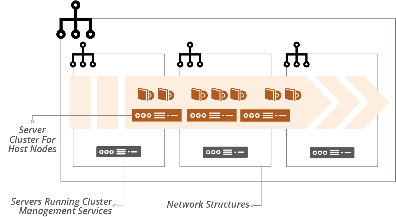
Figure 14-2. An example application cluster
Networking structures for an application cluster may be flat. The cluster services assign network addresses to application instances. It should also handle network security, including encryption and connection management, often using a service mesh for this.
You use infrastructure stacks to provision this infrastructure. Chapter 5 explained that the size of a stack and the scope of its contents have implications for the speed and risk of changes.
“Patterns and Antipatterns for Structuring Stacks” in particular lists patterns for arranging resources across stacks. The following examples show how these patterns apply to cluster infrastructure.
Monolithic Stack Using Cluster as a Service
The simplest design is to define all of the parts of your cluster in a single stack, following the monolithic stack antipattern (see “Antipattern: Monolithic Stack”). Although monoliths become an antipattern at scale, a single stack can be useful when starting out with a small and simple cluster.
Example 14-1 uses a cluster as a service, similar to AWS EKS, AWS ECS, Azure AKS, and Google GKE. So the code defines the cluster, but it doesn’t need to provision servers to run the cluster management, because the infrastructure platform handles that behind the scenes.
Example 14-1. Stack code that defines everything for a cluster
address_block:name:cluster_networkaddress_range:10.1.0.0/16"vlans:-vlan_a:address_range:10.1.0.0/8-vlan_b:address_range:10.1.1.0/8-vlan_c:address_range:10.1.2.0/8application_cluster:name:product_application_clusteraddress_block:$address_block.cluster_networkserver_cluster:name:"cluster_nodes"min_size:1max_size:3vlans:$address_block.cluster_network.vlanseach_server_node:source_image:cluster_node_imagememory:8GB
This example leaves out many of the things you’d have for a real cluster, like network routes, security policies, and monitoring. But it shows that the significant elements of networking, cluster definition, and server pool for host nodes are all in the same project.
Monolithic Stack for a Packaged Cluster Solution
The code in Example 14-1 uses an application cluster service provided by the infrastructure platform. Many teams instead use a packaged application cluster solution (as described in “Packaged Cluster Distribution”). These solutions have installers that deploy the cluster management software onto servers.
When using one of these solutions, your infrastructure stack provisions the infrastructure that the installer needs to deploy and configure the cluster. Running the installer should be a separate step. This way, you can test the infrastructure stack separately from the application cluster. Hopefully, you can define the configuration for your cluster as code. If so, you can manage that code appropriately, with tests and a pipeline to help you to deliver updates and changes easily and safely.
It may be useful to use server configuration code (as in Chapter 11) to deploy your cluster management system onto your servers. Some of the packaged products use standard configuration tools, such as Ansible for OpenShift, so you may be able to incorporate these into your stack building process. Example 14-2 shows a snippet that you would add to the monolithic stack code in Example 14-1 to create a server for the cluster management application.
Example 14-2. Code to build a cluster management server
virtual_machine:name:cluster_managersource_image:linux-basememory:4GBprovision:tool:servermakerparameters:maker_server:maker.shopspinner.xyzrole:cluster_manager
The code configures the server by running the fictitious servermaker command, applying the cluster_manager role.
Pipeline for a Monolithic Application Cluster Stack
Since there is only one stack, a single pipeline can test and deliver code changes to instances of the application cluster. However, there are other elements involved, including the server image for the host nodes and the applications themselves. Figure 14-3 shows a potential design for these pipelines.
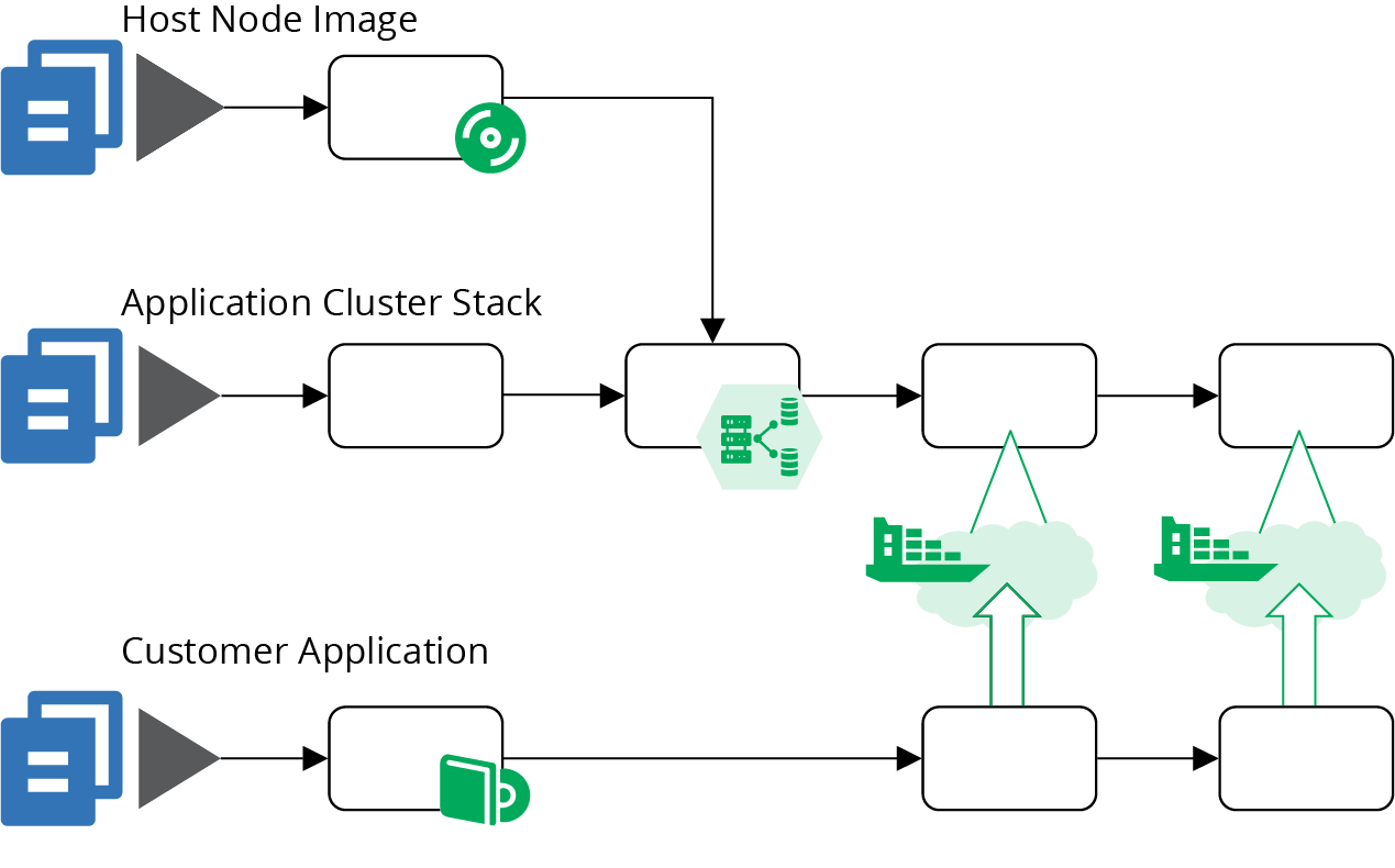
Figure 14-3. An example of pipelines for a cluster using a monolithic stack
The top pipeline (Figure 14-4) builds a server image for the host nodes, as described in “Using a Pipeline to Test and Deliver a Server Image”. The result of this pipeline is a server image that has been tested in isolation. The tests for that image probably check that the container management software is installed and that it complies with security policies.
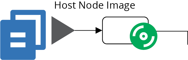
Figure 14-4. The pipeline for the host node server image
The bottom pipeline (Figure 14-5) is for an application that deploys onto the cluster. In practice, you’ll have a number of these, one for every separately deployed application. This pipeline includes at least one early stage to build and test the application on its own. It then has stages that deploy the application to the cluster in each environment. The application can be tested, reviewed, and made available for production use in these environments. The pipelines for the applications are very loosely coupled with the pipelines for the cluster instances. You may choose to trigger application testing stages after cluster updates. Doing this helps you to find any issues that the change to the cluster causes for the application by running the application-specific tests.
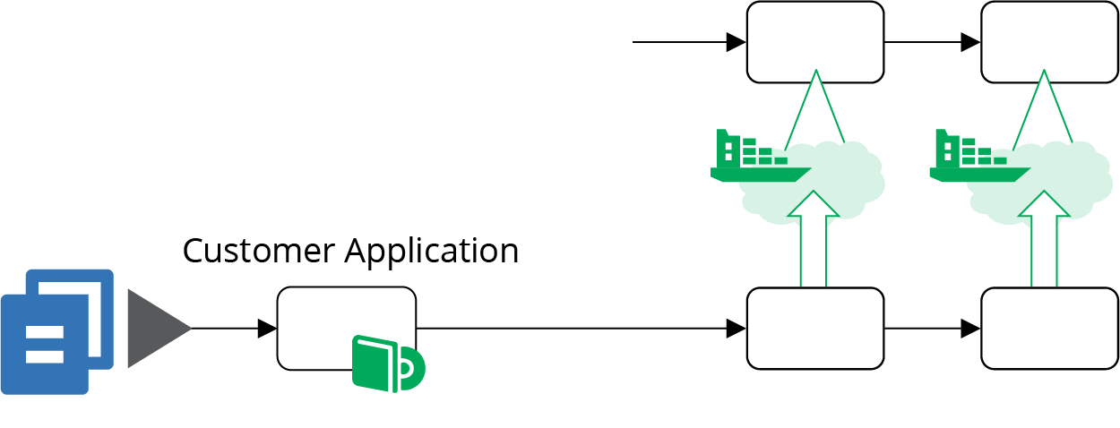
Figure 14-5. Pipelines for delivering applications to the cluster
The pipeline for the application cluster stack in Figure 14-6 starts with an offline stage (“Offline Testing Stages for Stacks”) that runs some syntax checking, and applies the stack code to a local mock of the infrastructure platform (“Testing with a Mock API”). These tests can catch problems at the coding level, without needing to use infrastructure platform resources, so they run quickly.
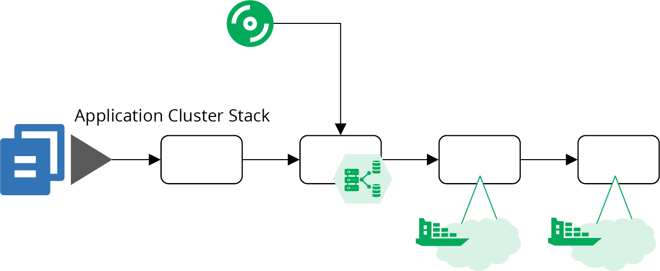
Figure 14-6. The pipeline for the cluster stack code
The second stage of this pipeline is an online stage (see “Online Testing Stages for Stacks”), and creates an instance of the stack on the infrastructure platform. The instance might be persistent (see “Pattern: Persistent Test Stack”) or ephemeral (see “Pattern: Ephemeral Test Stack”). The tests in this stage can check that the cluster management services are correctly created and accessible. You can also test for security issues—for instance, making sure that access to cluster management endpoints is locked down.3
Because this monolithic cluster stack includes the code to create the host node servers, the online testing stage can test these as well. A test could deploy a sample application to the cluster and prove that it’s working. The advantage of using a sample application rather than a real application is that you can keep it simple. Strip it down to a minimal set of dependencies and configurations, so you can be sure any test failures are caused by issues with the cluster provisioning, rather than due to complexities of deploying a real-world application.
Note that this pipeline stage is heavy. It tests both the cluster configuration and the host node server cluster. It also tests the server image in the context of the cluster. There are plenty of different things that can cause this stage to fail, which complicates troubleshooting and fixing failures.
Most of the elapsed time for this stage will almost certainly be taken up by provisioning everything, far more than the time to execute the tests. These two issues—the variety of things tested in this one stage, and the time it takes to provision—are the main drivers for breaking the cluster into multiple stacks.
Example of Multiple Stacks for a Cluster
Breaking the infrastructure code for a cluster into multiple stacks can improve the reliability and speed of your process for making changes. Aim to design each stack so that you can provision and test it in isolation, rather than needing to provision instances of other stacks.
Start by pulling the host node server pool into a separate stack, as in Example 14-3. You can provision and test an instance of this stack without the application cluster. Test that the platform successfully boots servers from your images and that network routes work correctly. You can also test reliability, triggering a problem with one of the servers and proving whether the platform automatically replaces it.
Example 14-3. Stack code that defines the server pool of host nodes
server_cluster:name:"cluster_nodes"min_size:1max_size:3vlans:$address_block.host_node_network.vlanseach_server_node:source_image:cluster_node_imagememory:8GBaddress_block:name:host_node_networkaddress_range:10.2.0.0/16"vlans:-vlan_a:address_range:10.2.0.0/8-vlan_b:address_range:10.2.1.0/8-vlan_c:address_range:10.2.2.0/8
This code adds separate VLANs for the host nodes, unlike the earlier code for the monolithic stack (see Example 14-1). It’s good practice to split the host nodes and the cluster management into different network segments, which you could do within the monolithic stack. Breaking the stacks apart leads us to do this, if only to reduce coupling between the two stacks.
Breaking the stacks apart adds a new pipeline for the host node cluster stack, as shown in Figure 14-7.
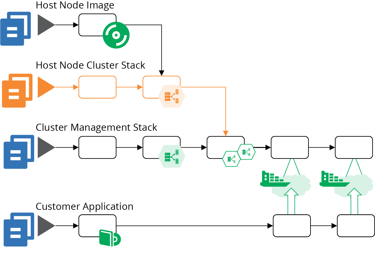
Figure 14-7. Added pipeline for the host node pool
Although there are a few more stages in this combined pipeline, they are lighter and faster. The online test stage for the cluster management stack (highlighted in Figure 14-8) only provisions the cluster management infrastructure, which is faster than the online stage in the monolithic stack pipeline. This stack no longer depends on the pipeline for host node server images, and doesn’t include the server nodes. So the tests in this stage can focus on checking that cluster management is configured and secured correctly.
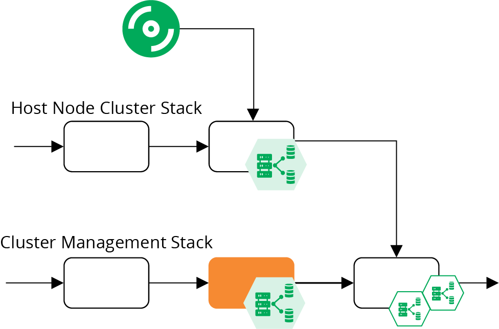
Figure 14-8. Online test stages for the cluster pipelines
This revised design joins the pipeline for the host node server stack together with the pipeline for the cluster management stack in a stack integration stage, as shown in Figure 14-9.
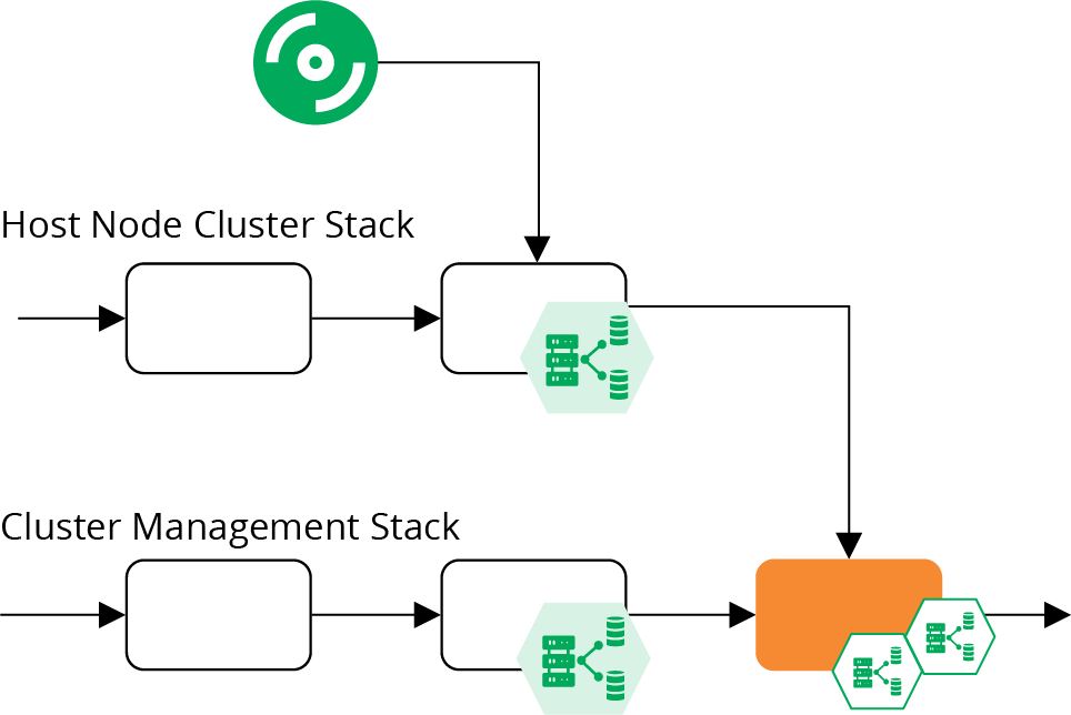
Figure 14-9. Stack integration test stage for a cluster
This is an online test stage that provisions and tests instances of both stacks together. These tests can focus on issues that only emerge with this combination, so shouldn’t duplicate testing activities from previous stages. This is the stage where you would deploy a sample application and prove that it runs correctly on the cluster. You could also test reliability and scaling by triggering failures in your test application and creating the conditions needed to add additional instances.
You might decide to split this into more stacks; for example, breaking the common networking infrastructure out of the management stack. Chapters 15 and 17 go into more details of decomposing and integrating infrastructure across stacks.
Sharing Strategies for Application Clusters
How many clusters should you run, how big should they be, and how much should you run on each?
In theory, you could run a single cluster, manifesting environments and other application boundaries within the cluster instance. However, there are many reasons why a single cluster may not be practical:4
- Managing changes
-
You need to update, upgrade, fix, and change your cluster. So at the least, you need somewhere to test these changes that won’t interrupt services. For disruptive changes, like those that require or risk downtime, scheduling a time that meets the needs of all teams, applications, and regions is challenging. Running multiple clusters makes it easier to schedule maintenance windows, and reduces the impact of a failed change.
- Segregation
-
Many clustering implementations don’t provide strong enough segregation between applications, data, and configuration. You may also have different governance regimes for the cluster implementation based on the services running on it. For example, services that handle credit card numbers may have stricter compliance requirements, so running them on a separate cluster simplifies the requirements for your other clusters.
- Configurability
-
Some applications or teams have different configuration requirements for the clusters they use. Providing them with separate cluster instances reduces configuration conflict.
- Performance and scalability
-
Clustering solutions have different scaling characteristics. Many don’t cope with higher latency, which makes it impractical to run a single cluster across geographical regions. Applications may hit resource limitations or contention issues with one another when they scale up on a single cluster.
- Availability
-
A single cluster is a single point of failure. Running multiple clusters can help cope with various failure scenarios.
There are a few potential strategies for sizing and sharing cluster instances. To choose the right strategy for your system, consider your requirements for change segregation, configurability, performance, scale, distribution, and availability. Then test your application clustering solution against those requirements.
One Big Cluster for Everything
A single cluster can be simpler to manage than multiple clusters. The likely exception is in managing changes. So at a minimum, you should use at least one separate cluster instance to test changes, using a pipeline to deploy and test cluster configuration changes there before applying them to your production cluster.
Separate Clusters for Delivery Stages
You can run different clusters for different parts of your software delivery process. Doing this could be as simple as running one cluster per environment (see Figure 14-10).
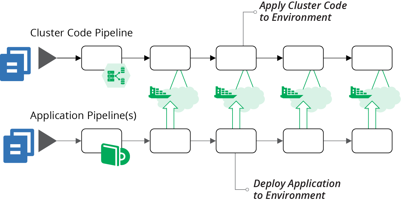
Figure 14-10. Pipelines managing one cluster for each application deployment environment
A dedicated cluster for every environment avoids inconsistencies you might get from having applications from multiple environments sharing resources. However, it may be difficult and expensive to maintain a separate instance for every delivery stage. For instance, if your delivery process dynamically creates test instances, you may need to dynamically create cluster instances to run them, which can be very slow.
A variation of separating clusters by delivery stage is to share clusters across multiple stages. For example, you might use different clusters based on governance requirements. In Figure 14-11, there are three clusters. The DEV cluster is for development, running instances where people create and use various data sets for more exploratory testing scenarios. The NON-PROD cluster is for more rigorous delivery stages, with managed test data sets. The PROD cluster hosts the PREPROD and PROD environments, both of which contain customer data and so have more rigorous governance
requirements.
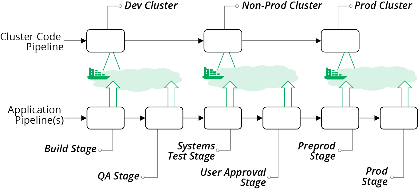
Figure 14-11. Cluster instances shared across multiple environments
When hosting multiple environments in a shared cluster, you should aim to keep each environment segregated as much as possible. Ideally, applications and operational services should not be able to see or interact with instances from other environments. Many of the mechanisms that application clustering solutions provide for separating applications are “soft.” For instance, you may be able to tag instances to indicate the environment, but this is purely a convention. You should look for stronger methods to segregate applications.
Clusters for Governance
One of the benefits of having separate clusters for different parts of the delivery process is that the governance requirements are usually different for different stages in the process. Production has tighter requirements because services running there are the most business-critical, and the data is the most sensitive.
Quite often, different parts of a system have different governance and compliance requirements that cut across delivery stages. The most common example is services that handle credit card numbers, which are subject to PCI standards. Other examples include services that deal with customer personal data, which may be subject to regimes such as GDPR.
Hosting services that are subject to stricter standards on dedicated clusters can simplify and strengthen compliance and auditing. You can impose stronger controls on these clusters, applications running on them, and delivery of code changes to them. Clusters hosting services with less strict compliance requirements can have streamlined governance processes and controls.
As an example, you could have two clusters, one used for development, testing, and production hosting for regulated services, and one for the unregulated services. Or you may split cluster instances by delivery stage and by regulation requirements, as illustrated in Figure 14-12.
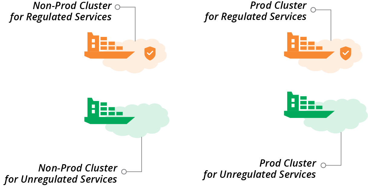
Figure 14-12. Separate clusters for delivery stage and regulation requirements
Clusters for Teams
Yet another factor for organizing multiple clusters is team ownership. Often, different teams are responsible for delivering and running different types of applications and services, which may have different hosting requirements. For example, a team owning customer-facing services may have different requirements for governance and availability than a team that owns services for an internal department. A cluster allocated to a team can be optimized for the requirements of that team and its applications.
Service Mesh
A service mesh is a decentralized network of services that dynamically manages connectivity between parts of a distributed system. It moves networking capabilities from the infrastructure layer to the application runtime layer of the model described in “The Parts of an Infrastructure System”. In a typical service mesh implementation, each application instance delegates communication with other instances to a sidecar process (see Figure 14-13).
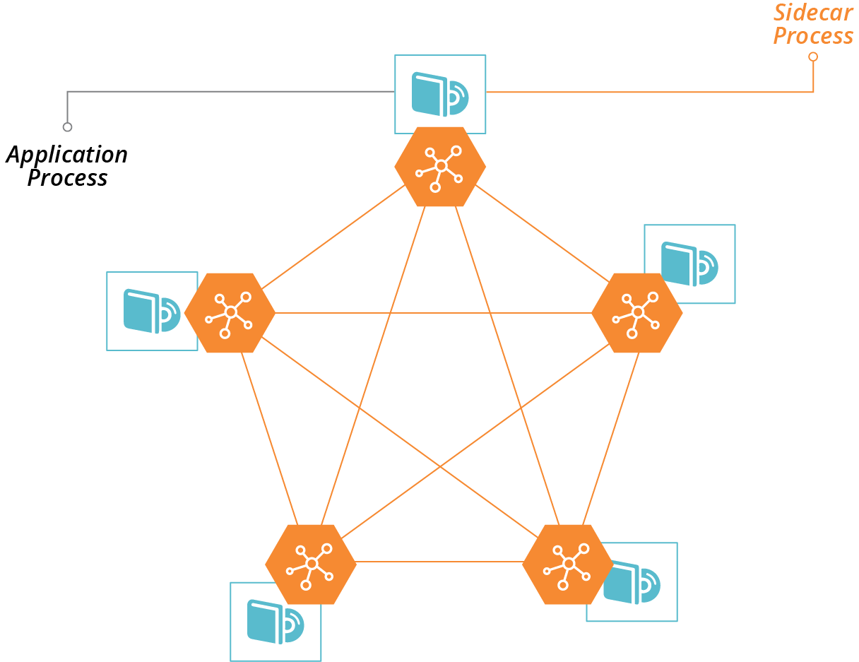
Figure 14-13. Sidecars enable communication with other processes in a service mesh
Some of the services that a service mesh can provide to applications include:
- Routing
-
Direct traffic to the most appropriate instance of a given application, wherever it is currently running. Dynamic routing with a service mesh enables advanced deployment scenarios, such as blue-green and canary, as described in “Changing Live Infrastructure”.
- Availability
-
Enforce rules for limiting numbers of requests; for example, circuit breakers.
- Security
-
Handle encryption, including certificates.
- Authentication
-
Enforce rules on which services can connect to which. Manage certificates for peer-to-peer authentication.
- Observability, monitoring, and troubleshooting
-
Record connections and other events so that people can trace requests through complex distributed systems.
A service mesh works well in combination with an application hosting cluster. The application cluster dynamically provides compute resources decoupled from lower-level resources. The service mesh dynamically manages application communication decoupled from lower-level networking resources. The benefits of this model are:
-
It simplifies application development, by moving common concerns out of the application and into the sidecar.
-
It makes it easier to build and improve common concerns across your estate, since you only need to deploy updates to the sidecar, without needing to make code changes to all of your applications and services.
-
It handles the dynamic nature of application deployment, since the same orchestration and scheduling system that deploys and configures application instances (e.g., in containers) can deploy and configure the sidecar instances along with them.
Some examples of service meshes include HashiCorp Consul, Envoy, Istio, and Linkerd.
Service meshes are most commonly associated with containerized systems. However, you can implement the model in noncontainerized systems; for example, by deploying sidecar processes onto virtual machines.
A service mesh adds complexity. As with cloud native architectural models like microservices, a service mesh is appealing because it simplifies the development of individual applications. However, the complexity does not disappear; you’ve only moved it out into the infrastructure. So your organization needs to be prepared to manage this, including being ready for a steep learning process.
It’s essential to keep clear boundaries between networking implemented at the infrastructure level, and networking implemented in the service mesh. Without a good design and implementation discipline, you may duplicate and intermingle concerns. Your system is harder to understand, riskier to change, and harder to troubleshoot.
Infrastructure for FaaS Serverless
Chapter 3 lists FaaS serverless as one of the ways a platform can provide compute resources to applications (see “Compute Resources”). The normal model for application code is to run it continuously in a container or server. FaaS executes application code on demand, in response to an event or schedule.
FaaS code is useful for well-defined, short-lived actions where the code starts quickly. Typical examples are handling HTTP requests or responding to error events in a message queue. The platform launches multiple instances of the code in parallel when needed, for example, to handle multiple events coming in simultaneously.
FaaS can be very efficient for workloads where the demand varies greatly, scaling up when there are peaks, and not running at all when not needed.
“Serverless” isn’t the most accurate term for this, because of course, the code does run on a server. It’s just that the server is effectively invisible to you as a developer. The same is true with containers, so what is distinctive about so-called serverless isn’t the level of abstraction from servers. The real distinction with serverless is that it is a short-lived process rather than a long-running process.
For this reason, many people prefer the term FaaS rather than serverless. This also disambiguates FaaS from other uses of the term serverless, which can also mean Backend as a Service (BaaS), which is an externally hosted service.5
FaaS runtimes follow the same models as application clusters—FaaS runtime provided as a service by your infrastructure platform, and packaged FaaS, which requires you to provision and configure infrastructure and management tools.
Examples of FaaS runtime provided as a service include:
Examples of packaged FaaS runtime solutions include:
You can use the same strategies described earlier in this chapter for provisioning infrastructure for a packaged FaaS solution, such as server pools and management services. Be sure you understand how your FaaS solution works in depth, so you are aware of whether and how code may “leak” data. For example, it may leave temporary files and other remnants in locations that may be available to other FaaS code, which can create issues for security and compliance. How well the FaaS solution meets your needs for segregating data, and whether it can scale, should drive your decisions on whether to run multiple instances of your FaaS runtime.
The FaaS services provided by cloud vendors usually don’t leave as much for you to configure as application clusters do. For example, you normally won’t need to specify the size and nature of the host servers the code executes on. This drastically reduces the amount of infrastructure you need to define and manage.
However, most FaaS code does interact with other services and resources. You may need to define networking for inbound requests that trigger a FaaS application, and for outbound requests the code makes. FaaS code often reads and writes data and messages to storage devices, databases, and message queues. These all require you to define and test infrastructure resources. And of course, FaaS code should be delivered and tested using a pipeline, as with any other code. So you still need all of the practices around defining and promoting infrastructure code and integrating it with application testing processes.
1 You can find a list of certified Kubernetes distributions on the Kubernetes website.
2 See “CF Container Runtime” for more details.
3 Kubernetes has historically had issues allowing the management API to be used without authentication. Follow guides to ensure you’re taking measures to secure your cluster, and write tests to stop code and configuration changes that accidentally create an opening for attackers.
4 Rob Hirschfeld explores the trade-offs between cluster sizes and sharing in his article, “The Optimal Kubernetes Cluster Size? Let’s Look at the Data”.
5 See Mike Roberts’s definitive article “Serverless Architectures” for more.