Chapter 2. How to Model Microservices
My opponent’s reasoning reminds me of the heathen, who, being asked on what the world stood, replied, “On a tortoise.” But on what does the tortoise stand? “On another tortoise.”
Rev. Joseph Frederick Berg (1854)
So you know what microservices are and, I hope, have a sense of their key benefits. You’re probably eager now to go and start making them, right? But where to start? In this chapter, we’ll look at some foundational concepts such as information hiding, coupling, and cohesion and understand how they’ll shift our thinking about drawing boundaries around our microservices. We’ll also look at different forms of decomposition you might use, as well as focusing more deeply on domain-driven design being a hugely useful technique in this space.
We’ll look at how to think about the boundaries of your microservices so as to maximize the upsides and avoid some of the potential downsides. But first, we need something to work with.
Introducing MusicCorp
Books about ideas work better with examples. Where possible, I’ll be sharing stories from real-world situations, but I’ve found it’s also useful to have a fictional scenario to work with. Throughout the book, we’ll be returning to this scenario, seeing how the concept of microservices works within this world.
So let’s turn our attention to the cutting-edge online retailer MusicCorp. MusicCorp was until recently just a brick-and-mortar retailer, but after the bottom dropped out of the vinyl record business, it focused more and more of its efforts online. The company has a website but feels that now is the time to double-down on the online world. After all, those smartphones for music are just a passing fad (Zunes are way better, obviously), and music fans are quite happy to wait for CDs to arrive at their doorsteps. Quality over convenience, right? And while it may have just learned that Spotify is in fact a digital music service rather than some sort of skin treatment for teenagers, MusicCorp is pretty happy with its own focus and is sure all of this streaming business will blow over soon.
Despite being a little behind the curve, MusicCorp has grand ambitions. Luckily, it has decided that its best chance of taking over the world is to make sure it can make changes as easily as possible. Microservices for the win!
What Makes a Good Microservice Boundary?
Before the team from MusicCorp tears off into the distance, creating service after service in an attempt to deliver eight-track tapes to all and sundry, let’s put the brakes on and talk a bit about the most important underlying idea we need to keep in mind. We want our microservices to be able to be changed and deployed, and their functionality released to our users, in an independent fashion. The ability to change one microservice in isolation from another is vital. So what things do we need to bear in mind when we think about how we draw the boundaries around them?
In essence, microservices are just another form of modular decomposition, albeit one that has network-based interaction between the models and all the associated challenges that brings. Luckily, this means we can rely on a lot of prior art in the space of modular software and structured programming to help guide us in terms of working out how to define our boundaries. With that in mind, let’s look more deeply at three key concepts that we touched on briefly in Chapter 1 and that are vital to grasp when it comes to working out what makes for a good microservice boundary—information hiding, cohesion, and coupling.
Information Hiding
Information hiding is a concept developed by David Parnas to look at the most effective way to define module boundaries.1 Information hiding describes a desire to hide as many details as possible behind a module (or, in our case, microservice) boundary. Parnas looked at the benefits that modules should theoretically give us, namely:
- Improved development time
-
By allowing modules to be developed independently, we can allow for more work to be done in parallel and reduce the impact of adding more developers to a project.
- Comprehensibility
-
Each module can be looked at in isolation and understood in isolation. This in turn makes it easier to understand what the system as a whole does.
- Flexibility
-
Modules can be changed independently from one another, allowing for changes to be made to the functionality of the system without requiring other modules to change. In addition, modules can be combined in different ways to deliver new functionality.
This list of desirable characteristics nicely complements what we are trying to achieve with microservice architectures—and indeed I now see microservices as just another form of modular architecture. Adrian Colyer has actually looked back at a number of David Parnas’s papers from this period and examined them with respect to microservices, and his summaries are well worth reading.2
The reality, as Parnas explored throughout much of his work, is that having modules doesn’t result in your actually achieving these outcomes. A lot depends on how the module boundaries are formed. From his own research, information hiding was a key technique to help get the most out of modular architectures, and with a modern eye, the same applies to microservices too.
From another of Parnas’s papers,3 we have this gem:
The connections between modules are the assumptions which the modules make about each other.
By reducing the number of assumptions that one module (or microservice) makes about another, we directly impact the connections between them. By keeping the number of assumptions small, it is easier to ensure that we can change one module without impacting others. If a developer changing a module has a clear understanding as to how the module is used by others, it will be easier for the developer to make changes safely in such a way that upstream callers won’t also have to change.
This applies with microservices, as well, except that we also have the opportunity to deploy that changed microservice without having to deploy anything else, arguably amplifying the three desirable characteristics that Parnas describes of improved development time, comprehensibility, and flexibility.
The implications of information hiding play out in so many ways, and I’ll pick up this theme throughout the book.
Cohesion
One of the most succinct definitions I’ve heard for describing cohesion is this: “the code that changes together, stays together.”4 For our purposes, this is a pretty good definition. As we’ve already discussed, we’re optimizing our microservice architecture around ease of making changes in business functionality—so we want the functionality grouped in such a way that we can make changes in as few places as possible.
We want related behavior to sit together, and unrelated behavior to sit elsewhere. Why? Well, if we want to change behavior, we want to be able to change it in one place, and to release that change as soon as possible. If we have to change that behavior in lots of different places, we’ll have to release lots of different services (perhaps at the same time) to deliver that change. Making changes in lots of different places is slower, and deploying lots of services at once is risky—thus we want to avoid both.
So we want to find boundaries within our problem domain that help ensure related behavior is in one place and that communicate with other boundaries as loosely as possible. If the related functionality is spread across the system, we say that cohesion is weak—whereas for our microservice architectures we’re aiming for strong cohesion.
Coupling
When services are loosely coupled, a change to one service should not require a change to another. The whole point of a microservice is being able to make a change to one service and deploy it without needing to change any other part of the system. This is really quite important.
What sorts of things cause tight coupling? A classic mistake is to pick an integration style that tightly binds one service to another, causing changes inside the service to require a change to consumers.
A loosely coupled service knows as little as it needs to about the services with which it collaborates. This also means we probably want to limit the number of different types of calls from one service to another, because beyond the potential performance problem, chatty communication can lead to tight coupling.
Coupling, though, comes in many forms, and I’ve seen a number of misunderstandings about the nature of coupling as it pertains to a service-based architecture. With that in mind, I think it’s important that we explore this topic in more detail, something we’ll do shortly.
The Interplay of Coupling and Cohesion
As we’ve already touched on, the concepts of coupling and cohesion are obviously related. Logically, if related functionality is spread across our system, changes to this functionality will ripple across those boundaries, implying tighter coupling. Constantine’s law, named for structured design pioneer Larry Constantine, sums this up neatly:
A structure is stable if cohesion is strong and coupling is low.5
The concept here of stability is important to us. For our microservice boundaries to deliver on the promise of independent deployability, allowing us to work on microservices in parallel and reduce the amount of coordination between teams working on these services, we need some degree of stability in the boundaries themselves. If the contract that a microservice exposes is constantly changing in a backward-incompatible fashion, then this will cause upstream consumers to constantly have to change too.
Coupling and cohesion are strongly related and, at some level at least, are arguably the same in that both concepts describe the relationship between things. Cohesion applies to the relationship between things inside a boundary (a microservice in our context), whereas coupling describes the relationship between things across a boundary. There is no absolute best way to organize our code; coupling and cohesion are just one way to articulate the various trade-offs we make around where we group code, and why. All we can strive to do is to find the right balance between these two ideas, one that makes the most sense for your given context and the problems you are currently facing.
Remember, the world isn’t static—it’s possible that as your system requirements change, you’ll find reasons to revisit your decisions. Sometimes parts of your system may be going through so much change that stability might be impossible. We’ll look at an example of this in Chapter 3 when I share the experiences of the product development team behind Snap CI.
Types of Coupling
You could infer from the preceding overview above that all coupling is bad. That isn’t strictly true. Ultimately, some coupling in our system will be unavoidable. What we want to do is reduce how much coupling we have.
A lot of work has been done to look at the different forms of coupling in the context of structured programming, which was largely considering modular (non-distributed, monolithic) software. Many of these different models for assessing coupling overlap or clash, and in any case they speak primarily about things at the code level, rather than considering service-based interactions. As microservices are a style of modular architecture (albeit with the added complexity of distributed systems), we can use a lot of these original concepts and apply them in the context of our microservice-based systems.
Not all the ideas map cleanly, so I have done my best to synthesize a working model for the different types of coupling for microservices. Where these ideas map cleanly to previous definitions, I’ve stuck with those terms. In other places I have had to come up with new terms or blend in ideas from elsewhere. So please consider what follows to be built on top of a lot of prior art in this space, which I am attempting to give more meaning in the context of microservices.
In Figure 2-1 we see a brief overview of the different types of coupling, organized from low (desirable) to high (undesirable).
Next, we’ll examine each form of coupling in turn, and look at examples that show how these forms may manifest themselves in our microservice architecture.
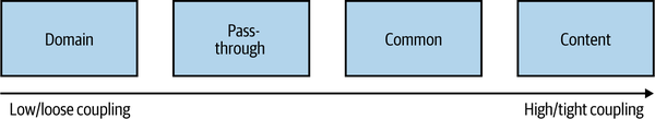
Figure 2-1. The different types of coupling, from loose (low) to tight (high)
Domain Coupling
Domain coupling describes a situation in which one microservice needs to interact with another microservice, because the first microservice needs to make use of the functionality that the other microservice provides.8
In Figure 2-2, we see part of how orders for CDs are managed inside MusicCorp. In this example, Order Processor calls the Warehouse microservice to reserve stock, and the Payment microservice to take payment. The Order Processor is therefore dependent on, and coupled to, the Warehouse and Payment microservices for this operation. We see no such coupling between Warehouse and Payment, though, as they don’t interact.
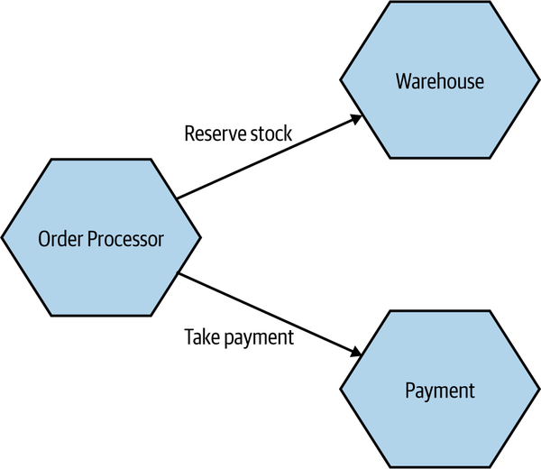
Figure 2-2. An example of domain coupling, where Order Processor needs to make use of the functionality provided by other microservices
In a microservice architecture, this type of interaction is largely unavoidable. A microservice-based system relies on multiple microservices collaborating in order for it to do its work. We still want to keep this to a minimum, though; whenever you see a single microservice depending on multiple downstream services in this way, it can be a cause for concern—it might imply a microservice that is doing too much.
As a general rule, domain coupling is considered to be a loose form of coupling, although even here we can hit problems. A microservice that needs to talk to lots of downstream microservices might point to a situation in which too much logic has been centralized. Domain coupling can also become problematic as more complex sets of data are sent between services—this can often point to the more problematic forms of coupling we’ll explore shortly.
Just remember the importance of information hiding. Share only what you absolutely have to, and send only the absolute minimum amount of data that you need.
Pass-Through Coupling
“Pass-through coupling”9 describes a situation in which one microservice passes data to another microservice purely because the data is needed by some other microservice further downstream. In many ways it’s one of the most problematic forms of implementation coupling, as it implies not only that the caller knows not just that the microservice it is invoking calls yet another microservice, but also that it potentially needs to know how that one-step-removed microservice works.
As an example of pass-through coupling, let’s look more closely now at part of how MusicCorp’s order processing works. In Figure 2-4, we have an Order Processor, which is sending a request to Warehouse to prepare an order for dispatch. As part of the request payload, we send along a Shipping Manifest. This Shipping Manifest contains not only the address of the customer but also the shipping type. The Warehouse just passes this manifest on to the downstream Shipping microservice.
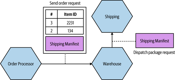
Figure 2-4. Pass-through coupling, in which data is passed to a microservice purely because another downstream service needs it
The major issue with pass-through coupling is that a change to the required data downstream can cause a more significant upstream change. In our example, if Shipping now needs the format or content of the data to be changed, then both Warehouse and Order Processor would likely need to change.
There are a few ways this can be fixed. The first is to consider whether it makes sense for the calling microservice to just bypass the intermediary. In our example, this might mean Order Processor speaks directly to Shipping, as in Figure 2-5. However, this causes some other headaches. Our Order Processor is increasing its domain coupling, as Shipping is yet another microservice it needs to know about—if that was the only issue, this might still be fine, as domain coupling is of course a looser form of coupling. This solution gets more complex here, though, as stock has to be reserved with Warehouse before we dispatch the package using Shipping, and after the shipping has been done we need to update the stock accordingly. This pushes more complexity and logic into Order Processor that was previously hidden inside Warehouse.
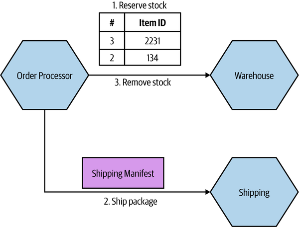
Figure 2-5. One way to work around pass-through coupling involves communicating directly with the downstream service
For this specific example, I might consider a simpler (albeit more nuanced) change—namely, to totally hide the requirement for a Shipping Manifest from Order Processor. The idea of delegating the work of both managing stock and arranging for dispatch of the package to our Warehouse service makes sense, but we don’t like the fact that we have leaked some lower-level implementation—namely, the fact that the Shipping microservice wants a Shipping Manifest. One way to hide this detail would be to have Warehouse take in the required information as part of its contract, and then have it construct the Shipping Manifest locally, as we see in Figure 2-6. This means that if the Shipping service changes its service contract, this change will be invisible from the viewpoint of Order Processor, as long as Warehouse collects the required data.
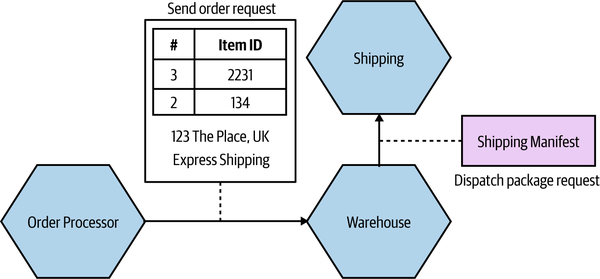
Figure 2-6. Hiding the need for a Shipping Manifest from the Order Processor
While this will help protect the Warehouse microservice from some changes to Shipping, there are some things that would still require all parties to change. Let’s consider the idea that we want to start shipping internationally. As part of this, the Shipping service needs a Customs Declaration to be included in the Shipping Manifest. If this is an optional parameter, then we could deploy a new version of the Shipping microservice without issue. If this is a required parameter, however, then Warehouse would need to create one. It might be able to do this with existing information that it has (or is given), or it might require that additional information be passed to it by the Order Processor.
Although in this case we haven’t eliminated the need for changes to be made across all three microservices, we have been given much more power over when and how these changes could be made. If we had the tight (pass-through) coupling of the initial example, adding this new Customs Declaration might require a lockstep rollout of all three microservices. At least by hiding this detail we could much more easily phase deployment.
One final approach that could help reduce the pass-through coupling would be for the Order Processor to still send the Shipping Manifest to the Shipping microservice via the Warehouse, but to have the Warehouse be totally unaware of the structure of the Shipping Manifest itself. The Order Processor sends the manifest as part of the order request, but the Warehouse makes no attempt to look at or process the
field—it just treats it like a blob of data and doesn’t care about the contents. Instead, it just sends it along. A change in the format of the the Shipping Manifest would still require a change to both the Order Processor and the Shipping microservice, but as the Warehouse doesn’t care about what is actually in the manifest, it doesn’t need to change.
Common Coupling
Common coupling occurs when two or more microservices make use of a common set of data. A simple and common example of this form of coupling would be multiple microservices making use of the same shared database, but it could also manifest itself in the use of shared memory or a shared filesystem.
The main issue with common coupling is that changes to the structure of the data can impact multiple microservices at once. Consider the example of some of MusicCorp’s services in Figure 2-7. As we discussed earlier, MusicCorp operates around the world, so it needs various bits of information about the countries in which it operates. Here, multiple services are all reading static reference data from a shared database. If the schema of this database changed in a backward-incompatible way, it would require changes to each consumer of the database. In practice, shared data like this tends to be very difficult to change as a result.
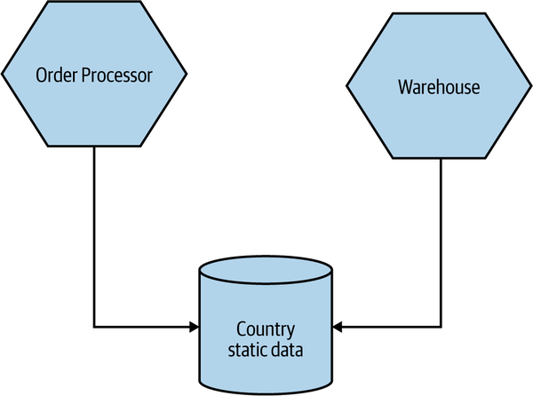
Figure 2-7. Multiple services accessing shared static reference data related to countries from the same database
The example in Figure 2-7 is, relatively speaking, fairly benign. This is because by its very nature static reference data doesn’t tend to change often, and also because this data is read-only—as a result I tend to be relaxed about sharing static reference data in this way. Common coupling becomes more problematic, though, if the structure of the common data changes more frequently, or if multiple microservices are reading and writing to the same data.
Figure 2-8 shows us a situation in which the Order Processor and Warehouse service are both reading and writing from a shared Order table to help manage the process of dispatching CDs to MusicCorp’s customers. Both microservices are updating the Status column. The Order Processor can set the PLACED, PAID, and COMPLETED statuses, whereas the Warehouse will apply PICKING or SHIPPED statuses.
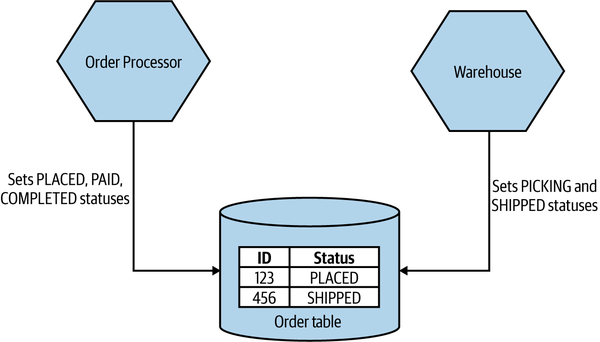
Figure 2-8. An example of common coupling in which both Order Processor and Warehouse are updating the same order record
Although you might consider Figure 2-8 to be somewhat contrived, this nonetheless straightforward example of common coupling helps illustrate a core problem. Conceptually, we have both the Order Processor and Warehouse microservices managing different aspects of the life cycle of an order. When making changes in Order Processor, can I be sure that I am not changing the order data in such a way that it breaks Warehouse’s view of the world, or vice versa?
One way to ensure that the state of something is changed in a correct fashion would be to create a finite state machine. A state machine can be used to manage the transition of some entity from one state to another, ensuring invalid state transitions are prohibited. In Figure 2-9, you can see the allowed transitions of state for an order in MusicCorp. An order can go directly from PLACED to PAID, but not straight from PLACED to PICKING (this state machine likely wouldn’t be sufficient for the real-world business processes involved in full end-to-end buying and shipping of goods, but I wanted to give a simple example to illustrate the idea).
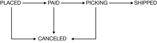
Figure 2-9. An overview of the allowable state transitions for an order in MusicCorp
The problem in this specific example is that both Warehouse and Order Processor share responsibilities for managing this state machine. How do we ensure that they are in agreement as to what transitions are allowed? There are ways to manage processes like this across microservice boundaries; we will return to this topic when we discuss sagas in Chapter 6.
A potential solution here would be to ensure that a single microservice manages the order state. In Figure 2-10, either Warehouse or Order Processor can send status update requests to the Order service. Here, the Order microservice is the source of truth for any given order. In this situation, it is really important that we see the requests from Warehouse and Order Processor as just that—requests. In this scenario, it is the job of the Order service to manage the acceptable state transitions associated with an order aggregate. As such, if the Order service received a request from Order Processor to move a status straight from PLACED to COMPLETED, it is free to reject that request if that is an invalid change.
Tip
Make sure you see a request that is sent to a microservice as something that the downstream microservice can reject if it is invalid.
An alternative approach I see in such cases is to implement the Order service as little more than a wrapper around database CRUD operations, where requests just map directly to database updates. This is akin to an object having private fields but public getters and setters—the behavior has leaked from the microservice to upstream consumers (reducing cohesion), and we’re back in the world of managing acceptable state transitions across multiple different services.
Warning
If you see a microservice that just looks like a thin wrapper around database CRUD operations, that is a sign that you may have weak cohesion and tighter coupling, as logic that should be in that service to manage the data is instead spread elsewhere in your system.
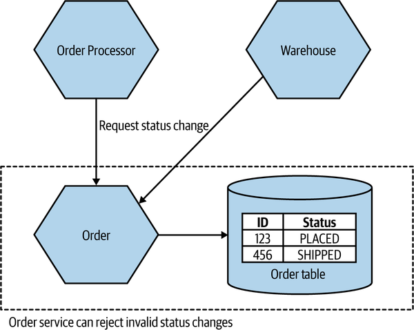
Figure 2-10. Both Order Processor and Warehouse can request that changes be made to an order, but the Order microservice decides which requests are acceptable
Sources of common coupling are also potential sources of resource contention. Multiple microservices making use of the same filesystem or database could overload that shared resource, potentially causing significant problems if the shared resource becomes slow or even entirely unavailable. A shared database is especially prone to this problem, as multiple consumers can run arbitrary queries against the database itself, which in turn can have wildly different performance characteristics. I’ve seen more than one database brought to its knees by an expensive SQL query—I may have even been the culprit once or twice.10
So common coupling is sometimes OK, but often it’s not. Even when it’s benign, it means that we are limited in what changes can be made to the shared data, but it often speaks to a lack of cohesion in our code. It can also cause us problems in terms of operational contention. It’s for those reasons that we consider common coupling to be one of the least desirable forms of coupling—but it can get worse.
Content Coupling
Content coupling describes a situation in which an upstream service reaches into the internals of a downstream service and changes its internal state. The most common manifestation of this is an external service accessing another microservice’s database and changing it directly. The differences between content coupling and common coupling are subtle. In both cases, two or more microservices are reading and writing to the same set of data. With common coupling, you understand that you are making use of a shared, external dependency. You know it’s not under your control. With content coupling, the lines of ownership become less clear, and it becomes more difficult for developers to change a system.
Let’s revisit our earlier example from MusicCorp. In Figure 2-11, we have an Order service that is supposed to manage the allowable state changes to orders in our system. The Order Processor is sending requests to the Order service, delegating not just the exact change in state that will be made but also responsibility for deciding what state transitions are allowable. On the other hand, the Warehouse service is directly updating the table in which order data is stored, bypassing any functionality in the Order service that might check for allowable changes. We have to hope that the Warehouse service has a consistent set of logic to ensure that only valid changes are made. At best, this represents a duplication of logic. In the worst case, the checking around allowable changes in Warehouse is different from that in the Order service, and as a result we could end up with orders in very odd, confusing states.
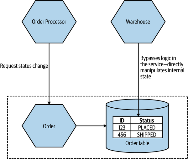
Figure 2-11. An example of content coupling in which the Warehouse is directly accessing the internal data of the Order service
In this situation, we also have the issue that the internal data structure of our order table is exposed to an outside party. When changing the Order service, we now have to be extremely careful about making changes to that particular table—that’s even assuming it’s obvious to us that this table is being directly accessed by an outside party. The easy fix here is to have the Warehouse send requests to the Order service itself, where we can vet the request but also hide the internal detail, making subsequent changes to the Order service much easier.
If you are working on a microservice, it’s vital that you have a clear separation between what can be changed freely and what cannot. To be explicit, as a developer you need to know when you are changing functionality that is part of the contract your service exposes to the outside world. You need to ensure that if you make changes, that you will not break upstream consumers. Functionality that doesn’t impact the contract your microservice exposes can be changed without concern.
It’s certainly the case that the problems that occur with common coupling also apply with content coupling, but content coupling has some additional headaches that make it problematic enough that some people refer to it as pathological coupling.
When you allow an outside party to directly access your database, the database in effect becomes part of that external contract, albeit one where you cannot easily reason about what can or cannot be changed. You’ve lost the ability to define what is shared (and therefore cannot be changed easily) and what is hidden. Information hiding has gone out of the window.
Just Enough Domain-Driven Design
As I introduced in Chapter 1, the primary mechanism we use for finding microservice boundaries is around the domain itself, making use of domain-driven design (DDD) to help create a model of our domain. Let’s now extend our understanding of how DDD works in the context of microservices.
The desire to have our programs better represent the real world in which they will operate is not new. Object-oriented programming languages like Simula were developed to allow us to model real domains. But it takes more than program language capabilities for this idea to really take shape.
Eric Evans’s Domain-Driven Design11 presented a series of important ideas that helped us better represent the problem domain in our programs. A full exploration of these ideas is outside the scope of this book, but there are some core concepts of DDD that are worth highlighting, including:
- Ubiquitous language
-
Defining and adopting a common language to be used in code and in describing the domain, to aid communication.
- Aggregate
-
A collection of objects that are managed as a single entity, typically referring to real-world concepts.
- Bounded context
-
An explicit boundary within a business domain that provides functionality to the wider system but that also hides complexity.
Ubiquitous Language
Ubiquitous language refers to the idea that we should strive to use the same terms in our code as the users use. The idea is that having a common language between the delivery team and the actual people will make it easier to model the real-world domain and also should improve communication.
As a counterexample, I recall a situation when working at a large, global bank. We were working in the area of corporate liquidity, a fancy term that basically refers to the ability to move cash among different accounts held by the same corporate entity. The product owner was really great to work with, and she had a fantastically deep understanding of the various products that she wanted to bring to market. When working with her, we’d have discussions about things like haircuts and end-of-day sweeps, all things that made a lot of sense in her world and that had meaning to her customers.
The code, on the other hand, had none of this language in there. At some point previously, a decision had been made to use a standard data model for the database. It was widely referred to as “the IBM banking model,” but I came to grips with whether this was a standard IBM product or just the creation of a consultant from IBM. By defining the loose concept of an “arrangement,” the theory went that any banking operation could be modeled. Taking out a loan? That was an arrangement. Buying a share? That’s an arrangement! Applying for a credit card? Guess what—that’s an arrangement too!
The data model had polluted the code to such an extent that the codebase was shorn of all real understanding of the system we were building. We weren’t building a generic banking application. We were building a system specifically to manage corporate liquidity. The problem was that we had to map the rich domain language of the product owner to the generic code concepts—meaning a lot of work in helping translate. Our business analysts were often just spending their time explaining the same concepts over and over again as a result.
By working the real-world language into the code, things became much easier. A developer picking up a story written using the terms that had come straight from the product owner was much more likely to understand their meaning and work out what needed to be done.
Aggregate
In DDD, an aggregate is a somewhat confusing concept, with many different definitions out there. Is it just an arbitrary collection of objects? The smallest unit that should be taken out of a database? The model that has always worked for me is to first consider an aggregate as a representation of a real domain concept—think of something like an Order, an Invoice, a Stock Item, and so on. Aggregates typically have a life cycle around them, which opens them up to being implemented as a state machine.
As an example in the MusicCorp domain, an Order aggregate might contain multiple line items that represent the items in the order. Those line items have meaning only as part of the overall Order aggregate.
We want to treat aggregates as self-contained units; we want to ensure that the code that handles the state transitions of an aggregate are grouped together, along with the state itself. So one aggregate should be managed by one microservice, although a single microservice might own management of multiple aggregates.
In general, though, you should think of an aggregate as something that has state, identity, a life cycle that will be managed as part of the system. Aggregates typically refer to real-world concepts.
A single microservice will handle the life cycle and data storage of one or more different types of aggregates. If functionality in another service wants to change one of these aggregates, it needs to either directly request a change in that aggregate or else have the aggregate itself react to other things in the system to initiate its own state transitions, perhaps by subscribing to events issued by other microservices.
The key thing to understand here is that if an outside party requests a state transition in an aggregate, the aggregate can say no. You ideally want to implement your aggregates in such a way that illegal state transitions are impossible.
Aggregates can have relationships with other aggregates. In Figure 2-12, we have a Customer aggregate that is associated with one or more Orders and one or more Wishlists. These aggregates could be managed by the same microservice or by different microservices.
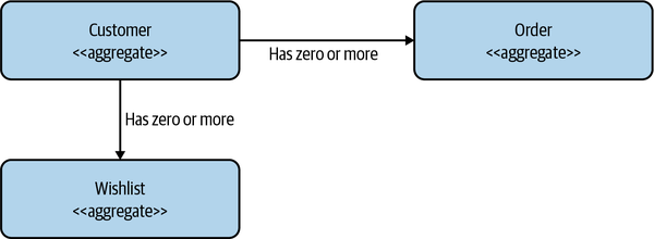
Figure 2-12. One Customer aggregate may be associated with one or more Order or Wishlist aggregates
If these relationships between aggregates exist inside the scope of a single microservice, they could easily be stored using something like a foreign key relationship if using a relational database. If the relationships between these aggregates span microservice boundaries, though, we need some way to model the relationships.
Now, we could simply store the ID of the aggregate directly in our local database. For example, consider a Finance microservice that manages a financial ledger, which stores transactions against a customer. Locally, within the Finance microservice’s database we could have a CustID column that contains the ID of that customer. If we wanted to get more information about that customer, we’d have to do a lookup against the Customer microservice using that ID.
The problem with this concept is that it isn’t very explicit—in fact, the relationship between the CustID column and the remote customer is entirely implicit. To know how that ID was being used, we’d have to look at the code of the Finance microservice itself. It would be nice if we could store a reference to a foreign aggregate in a way that is more obvious.
In Figure 2-13, we have changed things to make the relationship explicit. Rather than a vanilla ID for the customer reference, we instead store a URI, which we might use if building a REST-based system.12
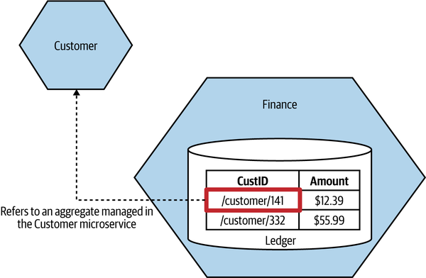
Figure 2-13. An example of how a relationship between two aggregates in different microservices can be implemented
The benefits of this approach are twofold. The nature of the relationship is explicit, and in a REST system we could directly dereference this URI to look up the associated resource. But what if you aren’t building a REST system? Phil Calçado describes a variation of this approach in use at SoundCloud,13 where they developed a pseudo-URI scheme for cross-service references. For example, soundcloud:tracks:123 would be a reference to a track with the ID of 123. This is much more explicit for a human looking at this identifier, but it is also a useful enough scheme that it would be easy to imagine creating code that could ease cross-microservice aggregate lookups if needed.
There are lots of ways to break a system into aggregates, with some choices being highly subjective. You may decide, for performance reasons or for ease of implementation, to reshape aggregates over time. I consider implementation concerns to be secondary, however; I begin by letting the mental model of the system users be my guiding light on initial design until other factors come into play.
Bounded Context
A bounded context typically represents a larger organizational boundary. Within the scope of that boundary, explicit responsibilities need to be carried out. That’s all a bit woolly, so let’s look at another specific example.
At MusicCorp, our warehouse is a hive of activity—managing orders being shipped out (and the odd return), taking delivery of new stock, having forklift truck races, and so on. Elsewhere, the finance department is perhaps less fun-loving but still has an important function inside our organization, handling payroll, paying for shipments, and the like.
Bounded contexts hide implementation detail. There are internal concerns—for example, the types of forklift trucks used are of little interest to anyone other than the folks in the warehouse. These internal concerns should be hidden from the outside world, which doesn’t need to know, nor should it care.
From an implementation point of view, bounded contexts contain one or more aggregates. Some aggregates may be exposed outside the bounded context; others may be hidden internally. As with aggregates, bounded contexts may have relationships with other bounded contexts—when mapped to services, these dependencies become inter-service dependencies.
Let’s return for a moment to the MusicCorp business. Our domain is the whole business in which we are operating. It covers everything from the warehouse to the reception desk, from finance to ordering. We may or may not model all of that in our software, but that is nonetheless the domain in which we are operating. Let’s think about parts of that domain that look like the bounded contexts to which Eric Evans refers.
Hidden models
For MusicCorp, we can consider the finance department and the warehouse to be two separate bounded contexts. They both have an explicit interface to the outside world (in terms of inventory reports, pay slips, etc.), and they have details that only they need to know about (forklift trucks, calculators).
The finance department doesn’t need to know about the detailed inner workings of the warehouse. It does need to know some things, however; for example, it needs to know about stock levels to keep the accounts up to date. Figure 2-14 shows an example context diagram. We see concepts that are internal to the warehouse, like a picker (someone who picks orders), shelves that represent stock locations, and so on. Likewise, entries in the general ledger are integral to finance but are not shared externally here.
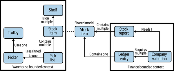
Figure 2-14. A shared model between the finance department and the warehouse
To be able to work out the valuation of the company, though, the finance employees need information about the stock we hold. The stock item then becomes a shared model between the two contexts. However, note that we don’t need to blindly expose everything about the stock item from the warehouse context. In Figure 2-15, we see how Stock Item inside the warehouse bounded context contains references to the shelf locations, but the shared representation contains only a count. So there is the internal-only representation and the external representation we expose. Often, when you have different internal and external representations, it may be beneficial to name them differently to avoid confusion—in this situation, one approach could be to call the shared Stock Item a Stock Count instead.
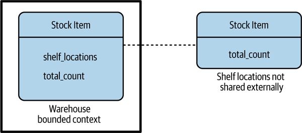
Figure 2-15. A model that is shared can decide to hide information that should not be shared externally
Shared models
We can also have concepts that appear in more than one bounded context. In Figure 2-14 we saw that a customer exists in both locations. What does this mean? Is the customer copied? The way to think about this is that conceptually, both finance and the warehouse need to know something about our customer. Finance needs to know about the financial payments made to a customer, whereas the warehouse needs to know about the customer to the extent that it knows what packages have been sent so as to allow for deliveries to be traced.
When you have a situation like this, a shared model like customer can have different meanings in the different bounded contexts and therefore might be called different things. We might be happy to keep the name “customer” in finance, but in the warehouse we might call them a “recipient,” as that is the role they play in that context. We store information about the customer in both locations, but the information is different. Finance stores information about the customer’s financial payments (or refunds); the warehouse stores information related to the goods shipped. We still may need to link both local concepts to a global customer, and we may want to look up common, shared information about that customer like their name or email address—we could use a technique like that shown in Figure 2-13 to achieve this.
Mapping Aggregates and Bounded Contexts to Microservices
Both the aggregate and the bounded context give us units of cohesion with well-defined interfaces with the wider system. The aggregate is a self-contained state machine that focuses on a single domain concept in our system, with the bounded context representing a collection of associated aggregates, again with an explicit interface to the wider world.
Both can therefore work well as service boundaries. When starting out, as I’ve already mentioned, you want to reduce the number of services you work with. As a result, you should probably target services that encompass entire bounded contexts. As you find your feet and decide to break these services into smaller services, you need to remember that aggregates themselves don’t want to be split apart—one microservice can manage one or more aggregates, but we don’t want one aggregate to be managed by more than one microservice.
Turtles all the way down
At the start, you will probably identify a number of coarse-grained bounded contexts. But these bounded contexts can in turn contain further bounded contexts. For example, you could decompose the warehouse into capabilities associated with order fulfillment, inventory management, or goods receiving. When considering the boundaries of your microservices, first think in terms of the larger, coarser-grained contexts, and then subdivide along these nested contexts when you’re looking for the benefits of splitting out these seams.
A trick here is that even if you decide to split a service that models an entire bounded context into smaller services later on, you can still hide this decision from the outside world—perhaps by presenting a coarser-grained API to consumers. The decision to decompose a service into smaller parts is arguably an implementation decision, so we might as well hide it if we can. In Figure 2-16 we see an example of this. We’ve split Warehouse down into Inventory and Shipping. As far as the outside world is concerned, there is still just the Warehouse microservice. Internally though, we’ve further decomposed things to allow Inventory to manage Stock Items and have Shipping manage Shipments. Remember, we want to keep the ownership of a single aggregate inside a single microservice.
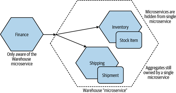
Figure 2-16. The Warehouse service internally has been split into Inventory and Shipping microservices
This is another form of information hiding—we’ve hidden a decision about internal implementation in such a way that if this implementation detail changes again in the future, our consumers will be unaware.
Another reason to prefer the nested approach could be to chunk up your architecture to simplify testing. For example, when testing services that consume the warehouse, I don’t have to stub each service inside the warehouse context—just the more coarse-grained API. This can also give you a unit of isolation when considering larger-scoped tests. I may, for example, decide to have end-to-end tests in which I launch all services inside the warehouse context, but for all other collaborators I might stub them out. We’ll explore more about testing and isolation in Chapter 9.
Event Storming
Event storming, a technique developed by Alberto Brandolini, is a collaborative brainstorming exercise designed to help surface a domain model. Rather than having an architect sit in a corner and come up with their own representation of what the domain model is,14 event storming brings together technical and nontechnical stakeholders in a joint exercise. The idea is that, by making the development of the domain model a joint activity, you end up with a shared, joined-up view of the world.
It’s worth mentioning at this point that while the domain models defined through event storming can be used to implement event-driven systems—and indeed, the mapping is very straightforward—you can also use such a domain model to build a more request/response-oriented system.
Logistics
Alberto has some very specific views as to how event storming should be run, and on some of these points I am very much in agreement. Firstly, get everyone in a room together. This is often the most difficult step—getting people’s calendars to line up can be a problem, as can finding a big enough room. Those issues were all true in a pre-COVID world, but as I write this during the virus-related lockdown in the UK, I’m aware that this step might be even more problematic in the future. The key, though, is to have all stakeholders present at the same time. You want representatives of all parts of the domain that you plan to model: users, subject matter experts, product owners—whoever is best placed to help represent each part of the domain.
Once everyone is in a room together, Alberto suggests the removal of all chairs to make sure everyone gets up and is involved. As someone with a bad back, while this strategy is something I understand, I recognize that it may not work for everyone. One thing I do agree with Alberto about is the need to have a large space where the modeling can be done. A common solution is to pin large rolls of brown paper to the walls of the room, allowing for all the walls to be used for capturing information.
The main modeling tool is sticky notes to capture the various concepts, with differently colored notes representing different concepts.
The process
The exercise starts with the participants identifying the domain events. These represent things that happen in the system—they are the facts that you care about. “Order Placed” would be an event that we would care about in the context of MusicCorp, as would “Payment Received.” These are captured on orange sticky notes. It is at this point that I have another disagreement with Alberto’s structure, as the events are far and away the most numerous things you’ll be capturing, and orange sticky notes are surprisingly hard to get hold of.15
Next, participants identify the commands that cause these events to happen. A command is a decision made by a human (a user of the software) to do something. Here you are trying to understand the system’s boundary, and identify the key human actors in the system. Commands are captured on blue sticky notes.
The techies in the event storming session should be listening to what their nontechnical colleagues come up with here. A key part of this exercise is not to let any current implementation warp the perception of what the domain is (that comes later). At this stage you want to create a space in which you can get the concepts out of the heads of the key stakeholders and out in the open.
With events and commands captured, aggregates come next. The events you have at this stage not only are useful for sharing not just what happens in the system, but they also start to highlight what the potential aggregates might be. Think of the aforementioned domain event “Order Placed.” The noun here—“Order”—could well be a potential aggregate. And “Placed” describes something that can happen to an order, so this may well be part of the life cycle of the aggregate. Aggregates are represented by yellow sticky notes, and the commands and events associated with that aggregate are moved and clustered around the aggregate. This also helps you understand how aggregates are related to each other—events from one aggregate might trigger behavior in another.
With the aggregates identified, they are grouped into bounded contexts. Bounded contexts most commonly follow a company’s organizational structure, and the participants of the exercise are well placed to understand what aggregates are used by which parts of the organization.
There is more to event storming than what I’ve just described—this was just meant as a brief overview. For a more detailed look at event storming, I’d suggest you read the (currently in progress) book EventStorming by Alberto Brandolini (Leanpub).16
The Case for Domain-Driven Design for Microservices
We’ve explored how DDD can work in the context of microservices, so let’s summarize how this approach is useful to us.
Firstly, a big part of what makes DDD so powerful is that bounded contexts, which are so important to DDD, are explicitly about hiding information—presenting a clear boundary to the wider system while hiding internal complexity that is able to change without impacting other parts of the system. This means that when we follow a DDD approach, whether we realize it or not, we are also adopting information hiding—and as we’ve seen, this is vital in helping to find stable microservice boundaries.
Secondly, the focus on defining a common, ubiquitous language helps greatly when it comes to defining microservice endpoints. It neatly gives us a shared vocabulary to draw on when coming up with APIs, event formats, and the like. It also helps solve the problem of how far the standardization of APIs needs to go in terms of allowing language to change within bounded contexts—change inside a boundary impacting that boundary itself.
The changes we implement to our system are often about changes the business wants to make in how the system behaves. We are changing functionality—capabilities—that are exposed to our customers. If our systems are decomposed along the bounded contexts that represent our domain, any changes we want to make are more likely to be isolated to a single microservice boundary. This reduces the number of places we need to make a change and allows us to deploy that change quickly.
Fundamentally, DDD puts the business domain at the heart of the software we are building. The encouragement that it gives us to pull the language of the business into our code and service design helps improve domain expertise among the people who build the software. This in turn helps build understanding and empathy for the users of our software and builds greater communication among technical delivery, product development, and the end users. If you are interested in moving toward stream-aligned teams, DDD fits in neatly as a mechanism to help align the technical architecture with the wider organizational structure. In a world in which we are increasingly trying to tear down the silos between IT and “the business,” this is no bad thing.
Alternatives to Business Domain Boundaries
As I’ve outlined, DDD can be incredibly useful when building microservice architectures, but it would be a mistake to think that this is the only technique you should consider when finding microservice boundaries. In fact, I often use multiple methods in conjunction with DDD to help identify how (and if) a system should be split. Let’s look at some of the other factors we might consider when finding boundaries.
Volatility
I’ve increasingly heard of pushback against domain-oriented decomposition, often by advocates for volatility being the primary driver for decomposition. Volatility-based decomposition has you identify the parts of your system going through more frequent change and then extract that functionality into their own services, where they can be more effectively worked on. Conceptually, I don’t have a problem with this, but promoting it as the only way to do things isn’t helpful, especially when we consider the different drivers that might be pushing us toward microservices. If my biggest issue is related to the need to scale my application, for example, a volatility-based decomposition is unlikely to deliver much of a benefit.
The mindset behind volatility-based decomposition is also evident in approaches like bimodal IT. A concept put forward by Gartner, bimodal IT neatly breaks the world down into the snappily named “Mode 1” (aka Systems of Record) and “Mode 2” (aka Systems of Innovation) categories based on how fast (or slow) different systems need to go. Mode 1 systems, we are told, don’t change much and don’t need much business involvement. Mode 2 is where the action is, with systems that need to change quickly and that require close involvement from the business. Putting aside for one moment the drastic oversimplification inherent in such a categorization scheme, it also implies a very fixed view of the world, and belies the sorts of transformations that are evident across industry as companies look to “go digital.” Parts of companies’ systems that didn’t need to change much in the past suddenly do, in order to open up new market opportunities and provide services to their customers in ways that they previously didn’t imagine.
Let’s come back to MusicCorp. Its first foray into what we now call digital was just having a web page; all it offered back in the mid-nineties was a listing of what was for sale, but you had to phone MusicCorp to place the order. It was little more than an advert in a newspaper. Then online ordering became a thing, and the entire warehouse, which up until that point had just been handled with paper, had to be digitized. Who knows—perhaps MusicCorp will at some stage have to consider making music available digitally! Although you might consider that MusicCorp is behind the times, you can still appreciate the amount of upheaval that companies have been going through as they understand how changing technology and customer behavior can require significant changes in parts of a business that couldn’t easily be foreseen.
I dislike bimodal IT as a concept, as it becomes a way for people to dump stuff that is hard to change into a nice neat box and say “we don’t need to deal with the issues in there—that’s Mode 1.” It’s yet another model that a company can adopt to ensure that nothing actually has to change. It also avoids the fact that quite often changes in functionality require changes in “Systems of Record” (Mode 1) to allow for changes in “Systems of Innovation” (Mode 2). In my experience, organizations adopting bimodal IT do end up having two speeds—slow and slower.
To be fair to proponents of volatility-based decomposition, many of them aren’t necessarily recommending such simplistic models as bimodal IT. In fact, I find this technique to be highly useful in helping to determine boundaries if the main driver is about fast time to market—extracting functionality that is changing or needs to change frequently makes perfect sense in such a situation. But again, the goal determines the most appropriate mechanism.
Data
The nature of the data you hold and manage can drive you toward different forms of decomposition. For example, you might want to limit which services handle personally identifiable information (PII), both to reduce your risk of data breaches and to simplify oversight and implementation of things like GDPR.
For one of my recent clients, a payment company we’ll call PaymentCo, the use of certain types of data directly influenced the decisions we made about system decomposition. PaymentCo handles credit card data, which means that its system needs to comply with various requirements set down by Payment Card Industry (PCI) standards for how this data needs to be managed. As part of this compliance, the company’s system and processes needed to be audited. PaymentCo had a need to handle the full credit card data, and at a volume that meant its system had to comply with PCI Level 1, which is the most stringent level and which requires quarterly external assessment of the systems and practices related to how the data is managed.
Many of the PCI requirements are common sense, but ensuring that the whole system complied with these requirements, not least the need for the system to be audited by an external party, was proving to be quite onerous. As a result, the company wanted to split out the part of the system that handled the full credit card data—meaning that only a subset of the system required this additional level of oversight. In Figure 2-17, we see a simplified form of the design we came up with. Services operating in the green zone (enclosed by a dotted green line) never see any credit card information—that data is limited to processes (and networks) in the red zone (surrounded by red dashes). The gateway diverts calls to the appropriate services (and the appropriate zone); as the credit card information passes through this gateway, it is in effect also in the red zone.
As credit card information never flows into the green zone, all services in this area can be exempted from a full PCI audit. Services in the red zone are in scope for such oversight. When working through the design, we did everything we could to limit what has to be in this red zone. It’s key to note that we had to make sure that the credit card information never flows to the green zone at all—if a microservice in the green zone could request this information, or if that information could be sent back to the green zone by a microservice in the red zone, then the clear lines of separation would break down.
Segregation of data is often driven by a variety of privacy and security concerns; we’ll come back to this topic and the example of PaymentCo in Chapter 11.
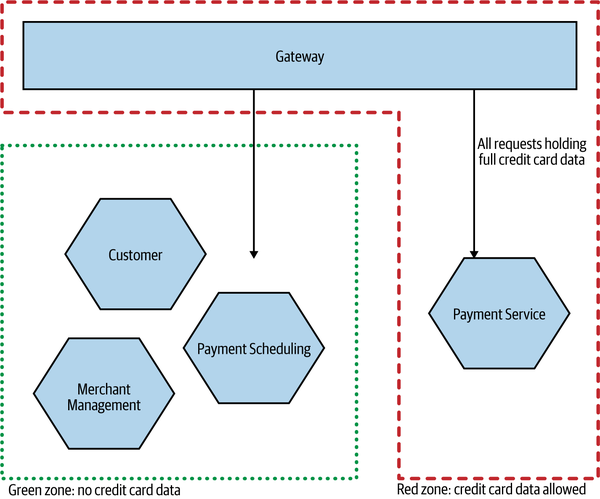
Figure 2-17. PaymentCo, which segregates processes based on its use of credit card information to limit the scope of PCI requirements
Technology
The need to make use of different technology can also be a factor in terms of finding a boundary. You can accommodate different databases in a single running microservice, but if you want to mix different runtime models, you may face a challenge. If you determine that part of your functionality needs to be implemented in a runtime like Rust, which enables you to eke out additional performance improvements, that ends up being a major forcing factor.
Of course, we have to be aware of where this can drive us if adopted as a general means of decomposition. The classic three-tiered architecture that we discussed in the opening chapter, and that we show again in Figure 2-18, is an example of related technology being grouped together. As we’ve already explored, this is often a less than ideal architecture.
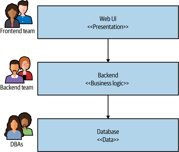
Figure 2-18. A traditional three-tiered architecture is often driven by technological boundaries
Organizational
As we established when I introduced Conway’s law back in Chapter 1, there is an inherent interplay between organizational structure and the system architecture you end up with. Quite aside from the studies that have shown this link, in my own anecdotal experience I have seen this play out time and time again. How you organize yourself ends up driving your systems architecture, for good or for ill. When it comes to helping us define our service boundaries, we have to consider this as a key part of our decision making.
Defining a service boundary whose ownership would cut across multiple different teams is unlikely to yield the outcomes we would desire—as we’ll explore further in Chapter 15, shared ownership of microservices is a fraught affair. It therefore follows that we must take into account the existing organizational structure when considering where and when to define boundaries, and in some situations we should perhaps even consider changing the organizational structure to support the architecture we want.
Of course, we also have to consider what happens if our organizational structure changes too. Does that mean we now have to rearchitect our software? Well, in the worst case, it might cause us to examine an existing microservice that now needs to be split, as it contains functionality that now may be owned by two separate teams, whereas before a single team was responsible for both parts. On the other hand, often organizational changes would just require that the owner of an existing microservice changes. Consider a situation in which the team in charge of warehousing operations previously also handled functionality around working out how many items should be ordered from suppliers. Let’s say that we decide to move this responsibility to a dedicated forecasting team that wants to pull information from current sales and planned promotions to work out what needs to be ordered. If the warehousing team had a dedicated Supplier Ordering microservice, this could just be moved to the new forecasting team. On the other hand, if this functionality was previously integrated into a larger-scoped system owned by warehousing, then it might need to be split out.
Even when we work within an existing organizational structure, there is a danger that we won’t get our boundaries in the right place. Many years ago, a few colleagues and I were working with a client in California, helping the company adopt some cleaner code practices and move more toward automated testing. We’d started with some of the low-hanging fruit, such as service decomposition, when we noticed something much more worrying. I can’t go into too much detail as to what the application did, but it was a public-facing application with a large, global customer base.
The team, and system, had grown. Originally one person’s vision, the system had taken on more and more features, and more and more users. Eventually, the organization decided to increase the capacity of the team by having a new group of developers based in Brazil take on some of the work. The system got split up, with the front half of the application being essentially stateless, implementing the public-facing website, as shown in Figure 2-19. The back half of the system was simply a remote procedure call (RPC) interface over a data store. Essentially, imagine you’d taken a repository layer in your codebase and made this a separate service.
Changes frequently had to be made to both services. Both services spoke in terms of low-level, RPC-style method calls, which were overly brittle (we’ll discuss this further in Chapter 4). The service interface was very chatty as well, resulting in performance issues. This led to the need for elaborate RPC-batching mechanisms. I called this “onion architecture,” as it had lots of layers and made me cry when we had to cut through it.
Now on the face of it, the idea of splitting the previously monolithic system along geographical/organizational lines makes perfect sense, as we’ll expand on in Chapter 15. Here, however, rather than taking a vertical, business-focused slice through the stack, the team picked what was previously an in-process API and made a horizontal slice. A better model would have been for the team in California to have one end-to-end vertical slice, consisting of the related parts of the frontend and data access functionality, with the team in Brazil taking another slice.
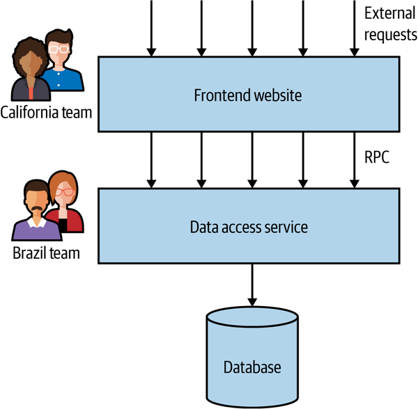
Figure 2-19. A service boundary split across technical seams
Mixing Models and Exceptions
As I hope is clear so far, I am not dogmatic in terms of how you find these boundaries. If you follow the guidelines of information hiding and appreciate the interplay of coupling and cohesion, then chances are you’ll avoid some of the worst pitfalls of whatever mechanism you pick. I happen to think that by focusing on these ideas you are more likely to end up with a domain-oriented architecture, but that is by the by. The fact is, though, that there can often be reasons to mix models, even if “domain-oriented” is what you decide to pick as your main mechanism for defining microservice boundaries.
The different mechanisms we’ve outlined so far also have a lot of potential interplay between them. Being too narrow in your choices here will cause you to follow the dogma rather than doing the right thing. Volatility-based decomposition can make a lot of sense if your focus is on improving the speed of delivery, but if this causes you to extract a service that crosses organizational boundaries, then expect your pace of change to suffer due to delivery contention.
I might define a nice Warehouse service based on my understanding of the business domain, but if one part of that system needs to be implemented in C++ and another part in Kotlin, then you’ll have to decompose further along those technical lines.
Organizational and domain-driven service boundaries are my own starting point. But that’s just my default approach. Typically, a number of the factors I’ve outlined here come into play, and which ones influence your own decisions will be based on the problems you are trying to solve. You need to look at your own specific circumstances to determine what works best for you—and hopefully I’ve given you a few different options to consider. Just remember, if someone says “The only way to do this is X!” they are likely just selling you more dogma. You can do better than that.
With all that said, let’s dive deeper into the topic of domain modeling by exploring domain-driven design in a little more detail.
Summary
In this chapter, you’ve learned a bit about what makes a good microservice boundary, and how to find seams in our problem space that give us the dual benefits of both low coupling and strong cohesion. Having a detailed understanding of our domain can be a vital tool in helping us find these seams, and by aligning our microservices to these boundaries we ensure that the resulting system has every chance of keeping those virtues intact. We’ve also gotten a hint about how we can subdivide our microservices further.
The ideas presented in Eric Evans’s Domain-Driven Design are very useful to us in finding sensible boundaries for our services, and I’ve just scratched the surface here—Eric’s book goes into much more detail. If you want to go deeper, I can recommend Vaughn Vernon’s book Implementing Domain-Driven Design17 to help you understand the practicalities of this approach, while Vernon’s Domain-Driven Design Distilled18 is a great condensed overview if you’re looking for something more brief.
Much of this chapter has described how we’d find the boundary for our microservices. But what happens if you already have a monolithic application and are looking to migrate toward a microservice architecture? That’s something we’ll explore in more detail in the next chapter.
1 David, Parnas, “On the Criteria to Be Used in Decomposing Systems into Modules,” (journal contribution, Carnegie Mellon University, 1971), https://oreil.ly/BnVVg.
2 The obvious starting point is Adrian’s summary of “On the Criteria…”, but Adrian’s coverage of Parnas’s earlier work, “Information Distribution Aspects of Design Methodology”, contains some great insights along with commentary from Parnas himself.
3 Parnas, “Information Distribution Aspects.”
4 Annoyingly, I cannot find the original source of this definition.
5 In my book Monolith to Microservices (O’Reilly) I attributed this to Larry Constantine himself. While the statement neatly sums up much of Constantine’s work in this space, the quote should really be attributed to Albert Endres and Dieter Rombach, from their 2003 book A Handbook of Software and Systems Engineering (Addison-Wesley).
6 Edward Yourdon and Larry L. Constantine, Structured Design (New York: Yourdon Press, 1976).
7 Meilir Page-Jones, The Practical Guide to Structured Systems Design (New York: Yourdon Press Computing, 1980).
8 This concept is similar to the domain application protocol, which defines the rules by which components interact in a REST-based system.
9 Pass-through coupling is my name for what was originally described as “tramp coupling” by Meilir Page-Jones in The Practical Guide to Structured Systems Design. I chose to use a different term here due to the fact that I found the original term to be somewhat problematic and not terribly meaningful to a wider audience.
10 OK, more than once or twice. A lot more than once or twice…
11 Eric Evans, Domain-Driven Design: Tackling Complexity in the Heart of Software (Boston: Addison-Wesley, 2004).
12 I know some people object to the use of templated URIs in REST systems, and I understand why—I just want to keep things simple for this example.
13 Phil Calçado, “Pattern: Using Pseudo-URIs with Microservices,” https://oreil.ly/xOYMr.
14 I mean no disrespect if this is you—I’ve done this myself more than once.
15 I mean, why not yellow? It’s the most common color!
16 Alberto Brandolini, EventStorming (Victoria, BC: Leanpub, forthcoming).
17 Vaughn Vernon, Implementing Domain-Driven Design (Upper Saddle River, NJ: Addison-Wesley, 2013).
18 Vaughn Vernon, Domain-Driven Design Distilled (Boston: Addison-Wesley, 2016).