12 Functional decomposition
12.1 Microservices
An application typically starts its life as a monolith. Take a modern backend of a single-page JavaScript application (SPA), for example. It might start out as a single stateless web service that exposes a RESTful HTTP API and uses a relational database as a backing store. The service is likely to be composed of a number of components or libraries that implement different business capabilities, as shown in Figure 12.1.
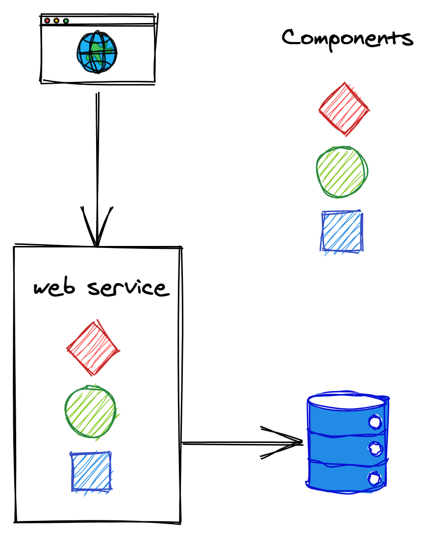
Figure 12.1: A monolithic backend composed of multiple components.
As the number of feature teams contributing to the same codebase increases, the components become increasingly coupled over time. This leads the teams to step on each other’s toes more and more frequently, decreasing their productivity.
The codebase becomes complex enough that nobody fully understands every part of it, and implementing new features or fixing bugs becomes time-consuming. Even if the backend is componentized into different libraries owned by different teams, a change to a library requires the service to be redeployed. And if a change introduces a bug like a memory leak, the entire service can potentially be affected by it. Additionally, rolling back a faulty build affects the velocity of all teams, not just the one that introduced the bug.
One way to mitigate the growing pains of a monolithic backend is to split it into a set of independently deployable services that communicate via APIs, as shown in Figure 12.2. The APIs decouple the services from each other by creating boundaries that are hard to violate, unlike the ones between components running in the same process.
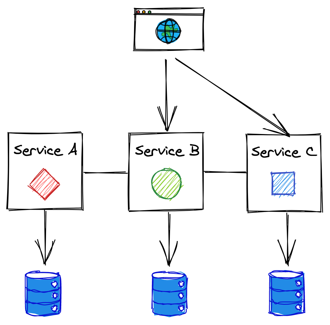
Figure 12.2: A backend split into independently deployable services that communicate via APIs.
This architectural style is also referred to as the microservice architecture. The term micro can be misleading, though — there doesn’t have to be anything micro about the services. In fact, I would argue that if a service doesn’t do much, it just creates more operational overhead than benefits. A more appropriate name for this architecture is service-oriented architecture, but unfortunately, that name comes with some old baggage as well. Perhaps in 10 years, we will call the same concept with yet another name, but for now we will have to stick to microservices.
12.1.1 Benefits
Breaking down the backend by business capabilities into a set of services with well-defined boundaries allows each service to be developed and operated by a single small team. Smaller teams can increase the application’s development speed for a variety of reasons:
- They are more effective as the communication overhead grows quadratically with the team’s size.
- Since each team dictates its own release schedule and has complete control over its codebase, less cross-team communication is required, and therefore decisions can be taken in less time.
- The codebase of a service is smaller and easier to digest by its developers, reducing the time it takes to ramp up new hires. Also, a smaller codebase doesn’t slow down IDEs as much, which makes developers more productive.
- The boundaries between services are much stronger than the boundaries between components in the same process. Because of that, when a developer needs to change a part of the backend, they only need to understand a small part of the whole.
- Each service can be scaled independently and adopt a different technology stack based on its own needs. The consumers of the APIs don’t care how the functionality is implemented after all. This makes it easy to experiment and evaluate new technologies without affecting other parts of the system.
- Each microservice can have its own independent data model and data store(s) that best fit its use-cases, allowing developers to change its schema without affecting other services.
12.1.2 Costs
The microservice architecture adds more moving parts to the overall system, and this doesn’t come for free. The cost of fully embracing microservices is only worth paying if it can be amortized across dozens of development teams.
Development experience
Nothing forbids the use of different languages, libraries, and datastores in each microservice, but doing so transforms the application into an unmaintainable mess. For example, it becomes more challenging for a developer to move from one team to another if the software stack is completely different. And think of the sheer number of libraries, one for each language adopted, that need to be supported to provide common functionality that all services need, like logging.
It’s only reasonable then that a certain degree of standardization is needed. One way to do that, while still allowing some degree of freedom, is to loosely encourage specific technologies by providing a great development experience for the teams that stick with the recommended portfolio of languages and technologies.
Resource provisioning
To support a large number of independent services, it should be simple to spin up new machines, data stores, and other commodity resources — you don’t want every team to come up with their own way of doing it. And once these resources have been provisioned, they have to be configured. To be able to pull this off, you will need a fair amount of automation.
Communication
Remote calls are expensive and come with all the caveats we discussed earlier in the book. You will need defense mechanisms to protect against failures and leverage asynchrony and batching to mitigate the performance hit of communicating across the network. All of this increases the system’s complexity.
Much of what is described in this book is about dealing with this complexity, and as it should be clear by now, it doesn’t come cheap. That being said, even a monolith doesn’t live in isolation since it’s being accessed by remote clients, and it’s likely to use third-party APIs as well. So eventually, these issues need to be solved there as well, albeit on a smaller scale.
Continuous integration, delivery, and deployment
Continuous integration ensures that code changes are merged into the main branch after an automated build and test suites have run. Once a code change has been merged, it should be automatically published and deployed to a production-like environment, where a battery of integration and end-to-end tests run to ensure that the service doesn’t break any dependencies or use cases.
While testing individual microservices is not more challenging than testing a monolith, testing the integration of all the microservices is an order of magnitude harder. Very subtle and unexpected behavior can emerge when individual services interact with each other.
Operations
Unlike with a monolith, it’s much more expensive to staff each team responsible for a service with its own operations team. As a result, the team that develops a service is typically also on-call for it. This creates friction between adding new features and operating the service as the team needs to decide what to prioritize during each sprint.
Debugging systems failures becomes more challenging as well, as you can’t just load the whole application on your local machine and step through it with a debugger. The system has more ways to fail, since there are more moving parts. This is why good logging and monitoring becomes crucial.
Eventual consistency
A side effect of splitting an application into separate services is that the data model no longer resides in a single data store. As we have learned in previous chapters, atomically updating records stored in different data stores, and guaranteeing strong consistency, is slow, expensive, and hard to get right. Hence, this type of architecture usually requires embracing eventual consistency.
12.1.3 Practical considerations
Splitting an application into services adds a lot of complexity to the overall system. Because of that, it’s generally best to start with a monolith and split it up only when there is a good reason to do so.
Getting the boundaries right between the services is challenging — it’s much easier to move them around within a monolith until you find a sweet spot. Once the monolith is well matured and growing pains start to rise, then you can start to peel off one microservice at a time from it.
You should only start with a microservice-first approach if you already have experience with it, and you either have built out a platform for it or have accounted for the time it will take you to build one.
12.2 API gateway
After you have split an application into a set of services, each with its own API, you need to rethink how clients communicate with the application. A client might need to perform multiple requests to different services to fetch all the information it needs to complete a specific operation. This can be very expensive on mobile devices where every network request consumes precious battery life.
Moreover, clients need to be aware of implementation details, like the DNS names of all the internal services. This makes it challenging to change the application’s architecture as it could require all clients to be upgraded. To make matters worse, if clients are distributed to individual consumers (e.g., an app on the App Store), there might not be an easy way to force them all to upgrade to a new version. The bottom line is that once a public API is out there, you better be prepared to maintain it for a very long time.
As is typical in computer science, we can solve this problem by adding a layer of indirection. The internal APIs can be hidden by a public one that acts as a facade, or proxy, for the internal services (see Figure 12.3). The service that exposes the public API is called the API gateway, which is transparent to its clients since they have no idea they are communicating through an intermediary.
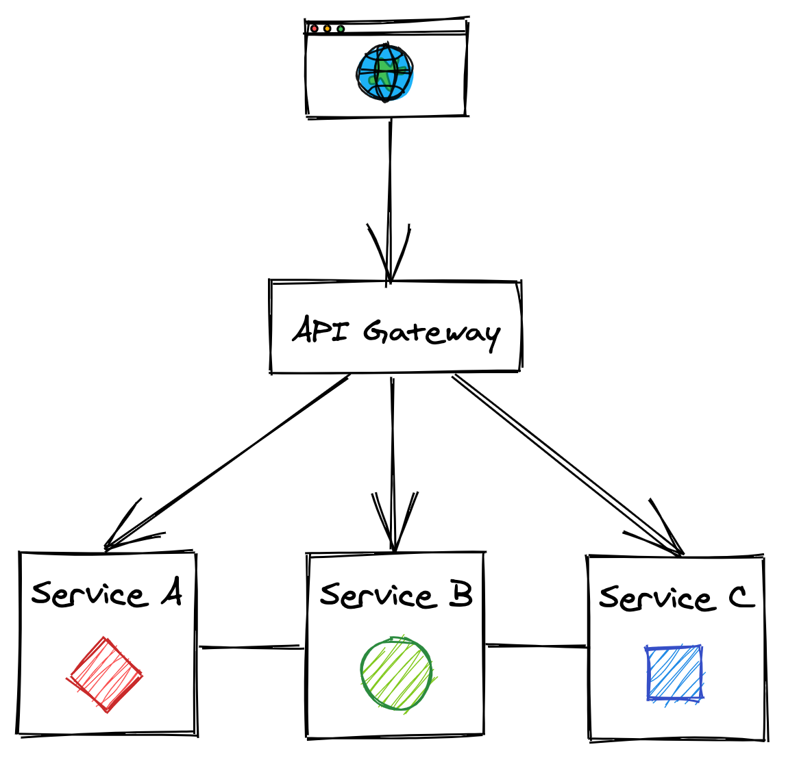
Figure 12.3: The API gateway hides the internal APIs from its clients.
The API gateway provides multiple features, like routing, composition, and translation.
12.2.1 Routing
The API gateway can route the requests it receives to the appropriate backend service. It does so with the help of a routing map, which maps the external APIs to the internal ones. For example, the map might have a 1:1 mapping between an external path and internal one. If in the future the internal path changes, the public API can continue to expose the old path to guarantee backward compatibility.
12.2.2 Composition
While data of a monolithic application typically resides in a single data store, in a distributed system, it’s spread across multiple services. As such, some use cases might require stitching data back together from multiple sources. The API gateway can offer a higher-level API that queries multiple services and composes their responses within a single one that is then returned to the client. This relieves the client from knowing which services to query and reduces the number of requests it needs to perform to get the data it needs.
Composition can be hard to get right. The availability of the composed API decreases as the number of internal calls increases since each has a non-zero probability of failure. Additionally, the data across the services might be inconsistent as some updates might not have propagated to all services yet; in that case, the gateway will have to somehow resolve this discrepancy.
12.2.3 Translation
The API gateway can translate from one IPC mechanism to another. For example, it can translate a RESTful HTTP request into an internal gRPC call.
The gateway can also expose different APIs to different types of clients. For example, a web API for a desktop application can potentially return more data than the one for a mobile application, as the screen estate is larger and more information can be presented at once. Also, network calls are expensive for mobile clients, and requests generally need to be batched to reduce battery usage.
To meet these different and competing requirements, the gateway can provide different APIs tailored to different use cases and translate these APIs to the internal ones. An increasingly popular approach to tailor APIs to individual use cases is to use graph-based APIs. A graph-based API exposes a schema composed of types, fields, and relationships across types. The API allows a client to declare what data it needs and let the gateway figure out how to translate the request into a series of internal API calls.
This approach reduces the development time as there is no need to introduce different APIs for different use cases, and the clients are free to specify what they need. There is still an API, though; it just happens that it’s described with a graph schema. In a way, it’s as if the gateway grants the clients the ability to perform restricted queries on its backend APIs. GraphQL is the most popular technology in the space at the time of writing.
12.2.4 Cross-cutting concerns
As the API gateway is a proxy, or middleman, for the services behind it, it can also implement cross-cutting functionality that otherwise would have to be re-implemented in each service. For example, the API gateway could cache frequently accessed resources to improve the API’s performance while reducing the bandwidth requirements on the services or rate-limit requests to protect the services from being overwhelmed.
Among the most critical cross-cutting aspects of securing a service, authentication and authorization are top-of-mind. Authentication is the process of validating that a so-called principal — a human or an application — issuing a request from a client is who it says it is. Authorization instead is the process of granting the authenticated principal permissions to perform specific operations, like creating, reading, updating, or deleting a particular resource. Typically this is implemented by assigning a principal one or more roles that grant specific permissions. Alternatively, an access control list can be used to grant specific principals access to specific resources.
A monolithic application can implement authentication and authorization with session tokens. A client sends its credentials to the application API’s login endpoint, which validates the credentials. If that’s successful, the endpoint returns a session token1 to the client, typically through an HTTP cookie. The client then includes the token in all future requests.
The application uses the session token to retrieve a session object from an in-memory cache or an external data store. The object contains the principal’s ID and the roles granted to it, which are used by the application’s API handlers to decide whether to allow the principal to perform an operation or not.
Translating this approach to a microservice architecture is not that straightforward. For example, it’s not obvious which service should be responsible for authenticating and authorizing requests, as the handling of requests can span multiple services.
One approach is to have the API gateway be responsible for authenticating external requests, since that’s their point of entry. This allows centralizing the logic to support different authentication mechanisms into a single component, hiding the complexity from internal services. In contrast, authorizing requests is best left to individual services to avoid coupling the API gateway with their domain logic.
When the API gateway has authenticated a request, it creates a security token. The gateway passes this token to the internal services responsible for handling the request, which in turn will pass it downstream to their dependencies (see Figure 12.4).
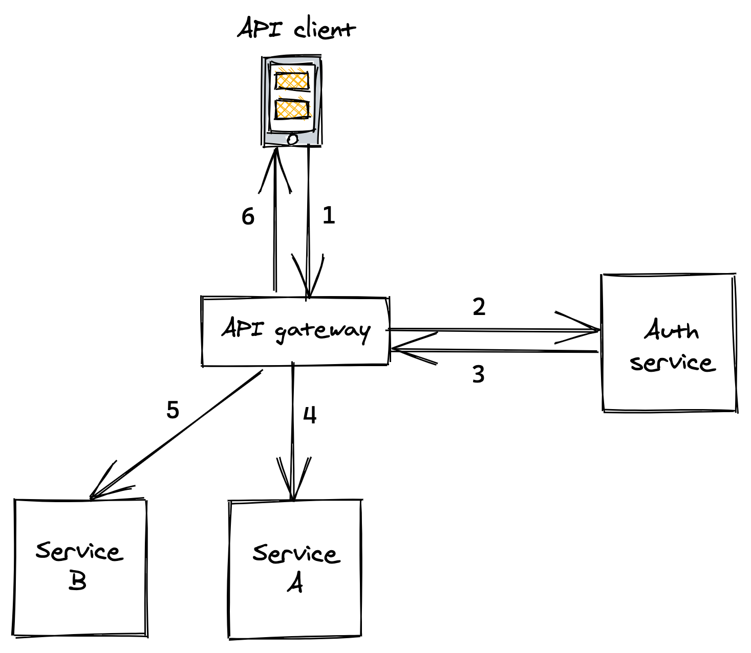
Figure 12.4: . API client sends a request with credentials to API gateway . API gateway tries to authenticate credentials with auth service . Auth service validates credentials and replies with a security token . API gateway sends a request to service A including the security token . API gateway sends a request to service B including the security token . API gateway composes the responses from A and B and replies to the client
When an internal service receives a request with a security token attached to it, it needs to have a way to validate it and obtain the principal’s identity and its roles. The validation differs depending on the type of token used, which can be either opaque and not contain any information (e.g., an UUID), or be transparent and embed the principal’s information within the token itself.
The downside of opaque tokens is that they require services to call an external auth service to validate a token and retrieve the principal’s information. Transparent tokens eliminate that call at the expense of making it harder to revoke issued tokens that have fallen into the wrong hands.
The most popular standard for transparent tokens is the JSON Web Token (JWT). A JWT is a JSON payload that contains an expiration date, the principal’s identity, roles, and other metadata. The payload is signed with a certificate trusted by internal services. Hence, no external calls are needed to validate the token.
OpenID Connect and OAuth 2 are security protocols that you can use to implement token-based authentication and authorization. We have barely scratched the surface on the topic, and there are entire books written on the subject you can read to learn more about it.
Another widespread mechanism to authenticate applications is the use API keys. An API key is a custom key that allows the API gateway to identify which application is making a request and limit what they can do. This approach is popular for public APIs, like the one offered by Github or Twitter.
12.2.5 Caveats
One of the drawbacks of using an API gateway is that it can become a development bottleneck. As it’s coupled with the services it’s hiding, every new service that is created needs to be wired up to it. Additionally, whenever the API of service changes, the gateway needs to be modified as well.
The other downside is that the API gateway is one more service that needs to be developed, maintained, and operated. Also, it needs to be able to scale to whatever the request rate is for all the services behind it. That said, if an application has dozens of services and APIs, the upside is greater than the downside and it’s generally a worthwhile investment.
So how do you go about implementing a gateway? You can roll your own API gateway, using a proxy framework as a starting point, like NGINX. Or better yet, you can use an off-the-shelf solution, like Azure API Management.
12.3 CQRS
The API’s gateway ability to compose internal APIs is quite limited, and querying data distributed across services can be very inefficient if the composition requires large in-memory joins.
Accessing data can also be inefficient for reasons that have nothing to do with using a microservice architecture:
- The data store used might not be well suited for specific types of queries. For example, a vanilla relational data store isn’t optimized for geospatial queries.
- The data store might not scale to handle the number of reads, which could be several orders of magnitude higher than the number of writes.
In these cases, decoupling the read path from the write path can yield substantial benefits. This approach is also referred to as the Command Query Responsibility Segregation (CQRS) pattern.
The two paths can use different data models and data stores that fit their specific use cases (see Figure 12.5). For example, the read path could use a specialized data store tailored to a particular query pattern required by the application, like geospatial or graph-based.
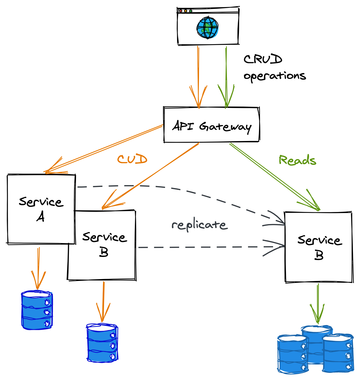
Figure 12.5: In this example, the read and write paths are separated out into different services.
To keep the read and write data models synchronized, the write path pushes updates to the read path whenever the data changes. External clients could still use the write path for simple queries, but complex queries are routed to the read path.
This separation adds more complexity to the system. For example, when the data model changes, both paths might need to be updated. Similarly, operational costs increase as there are more moving parts to maintain and operate. Also, there is an inherent replication lag between the time a change has been applied on the write path and the read path has received and applied it, which makes the system sequentially consistent.
12.4 Messaging
When an application is decomposed into services, the number of network calls increases, and with it, the probability that a request’s destination is momentarily unavailable. So far, we have mostly assumed services communicate using a direct request-response communication style, which requires the destination to be available and respond promptly. Messaging — a form of indirect communication — doesn’t have this requirement, though.
Messaging was first introduced when we discussed the implementation of asynchronous transactions in section 11.4.1. It is a form of indirect communication in which a producer writes a message to a channel — or message broker — that delivers the message to a consumer on the other end.
By decoupling the producer from the consumer, the former gains the ability to communicate with the latter even if it’s temporarily unavailable. Messaging provides several other benefits:
- It allows a client to execute an operation on a service asynchronously. This is particularly convenient for operations that can take a long time to execute. For example, suppose a video needs to be converted to multiple formats optimized for different devices. In that case, the client could write a message to a channel to trigger the conversion and be done with it.
- It can load balance messages across a pool of consumers, which can dynamically be added or removed to match the current load.
- It helps to smooth out load spikes allowing consumers to read messages at their own pace without getting overloaded.
Because there is an additional hop between the producer and consumer, the communication latency is necessarily going to be higher, more so if the channel has a large backlog of messages waiting to be processed. Additionally, the system’s complexity increases as there is one more service, the message broker, that needs to be maintained and operated — as always, it’s all about tradeoffs.
Any number of producers can write messages to a channel, and similarly, multiple consumers can read from it. Depending on how the channel delivers messages to consumers, it can be classified as either point-to-point or publish-subscribe. In a point-to-point channel, a specific message is delivered to exactly one consumer. Instead, in a publish-subscribe channel, a copy of the same message is delivered to all consumers.
A message channel can be used for a variety of different communication styles.
One-way messaging
In this messaging style, the producer writes a message to a point-to-point channel with the expectation that a consumer will eventually read and process it (see Figure 12.6).
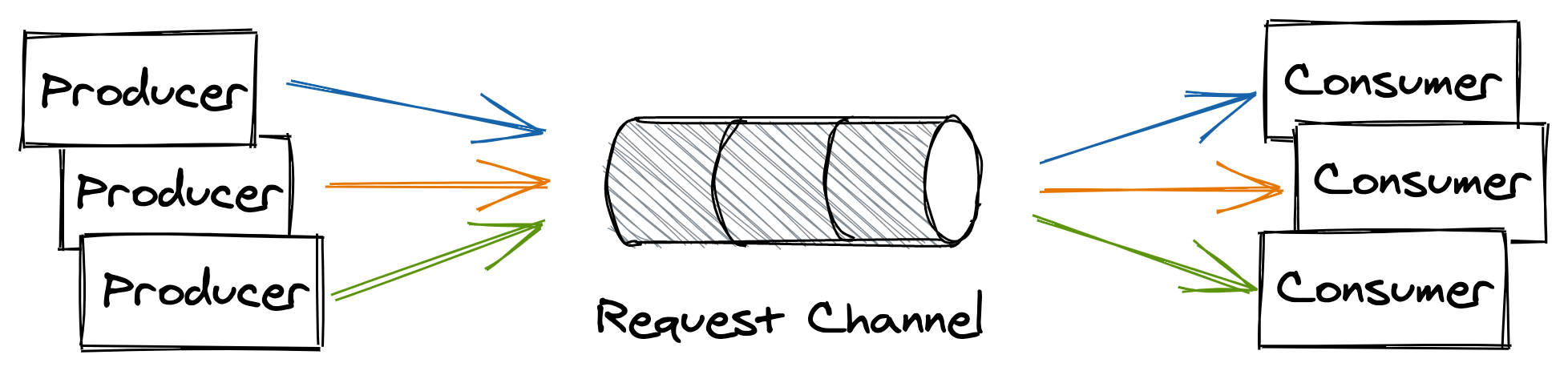
Figure 12.6: One-way messaging style
Request-response messaging
This messaging style is similar to the direct request-response style we are familiar with, albeit with the difference that the request and response messages flow through channels. The consumer has a point-to-point request channel from which it reads messages, while every producer has its own dedicated response channel (see Figure 12.7).
When a producer writes a message to the request channel, it decorates it with a request id and a reference to its response channel. After a consumer has read and processed the message, it writes a reply to the producer’s response channel, tagging it with the request’s id, which allows the producer to identify the request it belongs to.
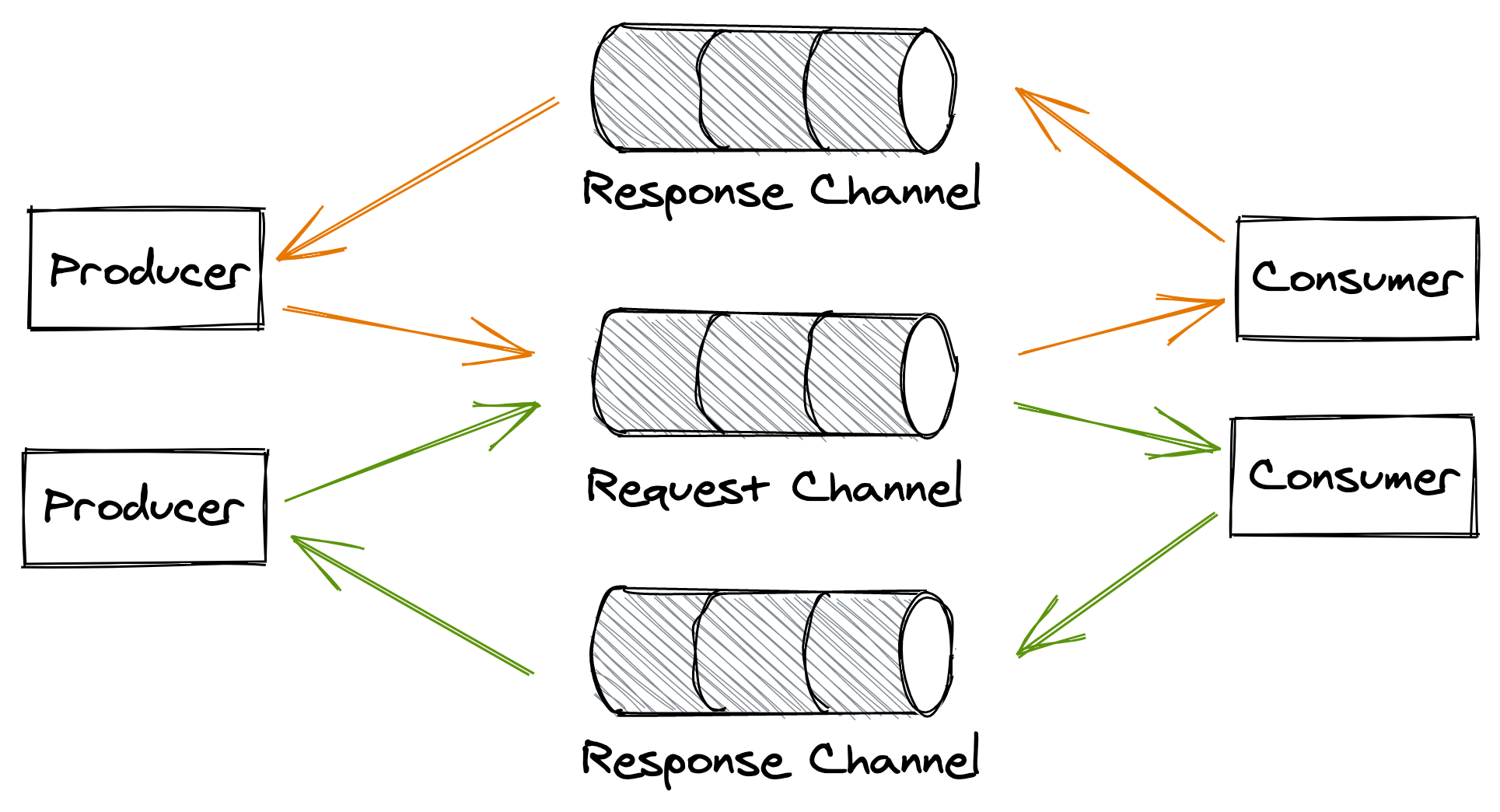
Figure 12.7: Request-response messaging style
Broadcast messaging
In this messaging style, a producer writes a message to a publish-subscribe channel to broadcast it to all consumers (see Figure 12.8). This mechanism is generally used to notify a group of processes that a specific event has occurred. We have already encountered this pattern when discussing log-based transactions in section 11.4.1.
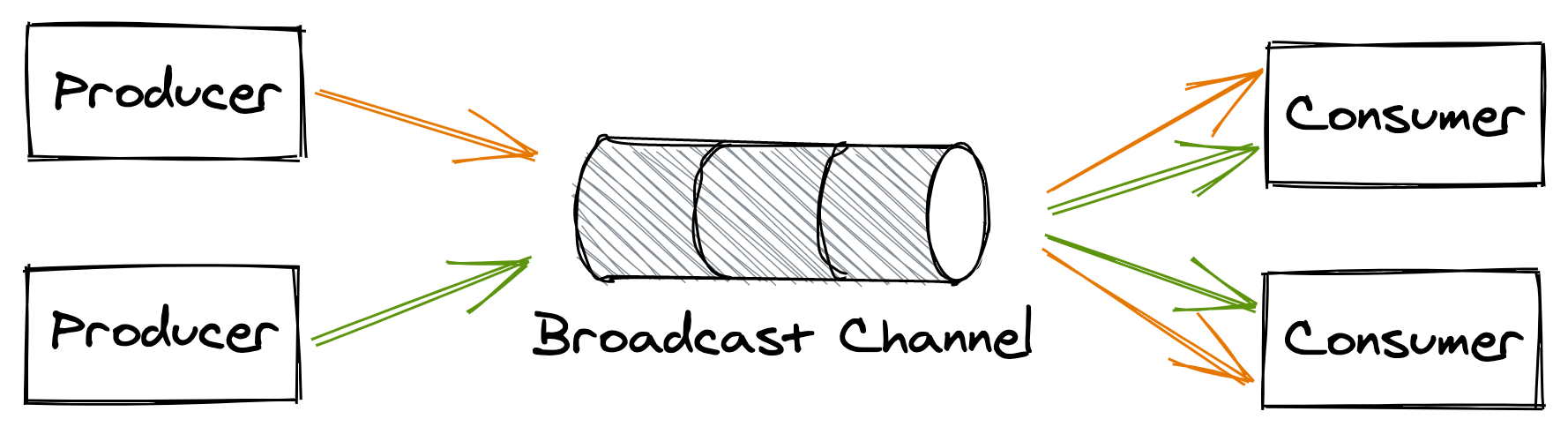
Figure 12.8: Broadcast messaging style
12.4.1 Guarantees
A message channel is implemented by a messaging service, like AWS SQS or Kafka. The messaging service, or broker, acts as a buffer for messages. It decouples producers from consumers so that they don’t need to know the consumers’ addresses, how many of them there are, or whether they are available.
Different message brokers implement the channel abstraction differently depending on the tradeoffs and the guarantees they offer. For example, you would think that a channel should respect the insertion order of its messages, but you will find that some implementations, like SQS standard queues, don’t offer any strong ordering guarantees. Why is that?
Because a message broker needs to scale out just like the applications that use it, its implementation is necessarily distributed. And when multiple nodes are involved, guaranteeing order becomes challenging as some form of coordination is required. Some brokers, like Kafka, partition a channel into multiple sub-channels, each small enough to be handled entirely by a single process. The idea is that if there is a single broker process responsible for the messages of a sub-channel, then it should be trivial to guarantee their order.
In this case, when messages are sent to the channel, they are partitioned into sub-channels based on a partition key. To guarantee that the message order is preserved end-to-end, only a single consumer process can be allowed to read from a sub-channel2.
Because the channel is partitioned, it suffers from several drawbacks. For example, a specific partition can become much hotter than the others, and the single consumer reading from it might not be able to keep up with the load. In that case, the channel needs to be repartitioned, which can temporarily degrade the broker since messages need to be reshuffled across all partitions. Later in the chapter, we will learn more about the pros and cons of partitioning.
Now you see why not having to guarantee the order of messages makes the implementation of a broker much simpler. Ordering is just one of the many tradeoffs a broker needs to make, such as:
- delivery guarantees, like at-most-once or at-least-once;
- message durability guarantees;
- latency;
- messaging standards supported, like AMQP;
- support for competing consumers;
- broker limits, such as the maximum supported size of messages.
Because there are so many different ways to implement channels, in the rest of this section we will make some assumptions for the sake of simplicity:
- Channels are point-to-point and support an arbitrary number of producers and consumers.
- Messages are delivered to consumers at-least-once.
- While a consumer is processing a message, the message remains persisted in the channel, but other consumers can’t read it for the duration of a visibility timeout. The visibility timeout guarantees that if the consumer crashes while processing the message, the message will become visible to other consumers again when the timeout triggers. When the consumer is done processing the message, it deletes it from the channel preventing it from being received by any other consumer in the future.
The above guarantees are very similar to what cloud services such as Amazon’s SQS and Azure Storage Queues offer.
12.4.2 Exactly-once processing
As mentioned, a consumer has to delete a message from the channel once it’s done processing it so that it won’t be read by another consumer.
If the consumer deletes the message before processing it, there is a risk it could crash after deleting the message and before processing it, causing the message to be lost for good. On the other hand, if the consumer deletes the message only after processing it, there is a risk that the consumer might crash after processing the message but before deleting it, causing the same message to be read again later on.
Because of that, there is no such thing as exactly-once message delivery. The best a consumer can do is to simulate exactly-once message processing by requiring messages to be idempotent.
12.4.3 Failures
When a consumer fails to process a message, the visibility timeout triggers, and the message is eventually delivered to another consumer. What happens if processing a specific message consistently fails with an error, though? To guard against the message being picked up repeatedly in perpetuity, we need to limit the maximum number of times the same message can be read from the channel.
To enforce a maximum number of retries, the broker can stamp messages with a counter that keeps track of the number of times the message has been delivered to a consumer. If the broker doesn’t support this functionality out of the box, it can be implemented by the consumers.
Once you have a way to count the number of times a message has been retried, you still have to decide what to do when the maximum is reached. A consumer shouldn’t delete a message without processing it, as that would cause data loss. But what it can do is remove the message from the channel after writing it to a dead letter channel — a channel that acts as a buffer for messages that have been retried too many times.
This way, messages that consistently fail are not lost forever but merely put on the side so that they don’t pollute the main channel, wasting consumers’ processing resources. A human can then inspect these messages to debug the failure, and once the root cause has been identified and fixed, move them back to the main channel to be reprocessed.
12.4.4 Backlogs
One of the main advantages of using a messaging broker is that it makes the system more robust to outages. Producers can continue to write messages to a channel even if one or more consumers are not available or are degraded. As long as the rate of arrival of messages is lower or equal to the rate they are being deleted from the channel, everything is great. When that is no longer true, and consumers can’t keep up with producers, a backlog starts to build up.
A messaging channel introduces a bi-modal behavior in the system. In one mode, there is no backlog, and everything works as expected. In the other, a backlog builds up, and the system enters a degraded state. The issue with a backlog is that the longer it builds up, the more resources and/or time it will take to drain it.
There are several reasons for backlogs, for example:
- more producers came online, and/or their throughput increased, and the consumers can’t match their rate;
- the consumers have become slower to process individual messages, which in turn decreased their deletion rate;
- the consumers fail to process a fraction of the messages, which are picked up again by other consumers until they eventually end up in the dead letter channel. This can cause a negative feedback loop that delays healthy messages and wastes the consumers’ processing time.
To detect backlogs, you should measure the average time a message waits in the channel to be read for the first time. Typically, brokers attach a timestamp of when the message was first written to it. The consumer can use that timestamp to compute how long the message has been waiting in the channel by comparing it to the timestamp taken when the message was read. Although the two timestamps have been generated by two physical clocks that aren’t perfectly synchronized (see section 8.1), the measure still provides a good indication of the backlog.
12.4.5 Fault isolation
A specific producer that emits “poisonous” messages that repeatedly fail to be processed can degrade the whole system and potentially cause backlogs, since messages are processed multiple times before they end up in the dead-letter channel. Therefore, it’s important to find ways to deal with problematic producers before they start to affect the rest of the system3.
If messages belong to different users4 and are decorated with some kind of identifier, consumers can decide to treat “noisy” users differently. For example, suppose messages from a specific user fail consistently. In that case, the consumers could decide to write these messages to an alternate low-priority channel and remove them from the main channel without processing them. The consumers can continue to read from the slow channel, but do so less frequently. This ensures that one single bad user can’t affect others.
12.4.6 Reference plus blob
Transmitting a large binary object (blob) like images, audio files, or video can be challenging or simply impossible, depending on the medium. For example, message brokers limit the maximum size of messages that can be written to a channel; Azure Storage queues limit messages to 64 KB, AWS Kinesis to 1 MB, etc. So how do you transfer large blobs of hundreds of MBs with these strict limits?
You can upload a blob to an object storage service, like AWS S3 or Azure Blob Storage, and then send the URL of the blob via message (this pattern is sometimes referred to as queue plus blob). The downside is that now you have to deal with two services, the message broker and the object store, rather than just the message broker, which increases the system’s complexity.
A similar approach can be used to store large blobs in databases — rather than storing a blob in a database directly, you only store some metadata containing an external reference to the actual blob. The advantage of this solution is that it minimizes data being transferred back and forth to and from the data store, improving its performance while reducing the required bandwidth. Also, the cost per byte of an object store designed to persist large objects that infrequently change, if at all, is lower than the one of a generic data store.
Of course, the downside is that you lose the ability to transactionally update the blob with its metadata and potentially other records in the data store. For example, suppose a transaction inserts a new record in the data store containing an image. In this case, the image won’t be visible until the transaction completes; that won’t be the case if the image is stored in an external store, though. Similarly, if the record is later deleted, the image is automatically deleted as well; but if the image lives outside the store, it’s your responsibility to delete it.
Whether storing blobs outside of your data store is acceptable or not depends on your specific use cases.