2 Reliable links
TCP is a transport-layer protocol that exposes a reliable communication channel between two processes on top of IP. TCP guarantees that a stream of bytes arrives in order, without any gaps, duplication or corruption. TCP also implements a set of stability patterns to avoid overwhelming the network or the receiver.
2.1 Reliability
To create the illusion of a reliable channel, TCP partitions a byte stream into discrete packets called segments. The segments are sequentially numbered, which allows the receiver to detect holes and duplicates. Every segment sent needs to be acknowledged by the receiver. When that doesn’t happen, a timer fires on the sending side, and the segment is retransmitted. To ensure that the data hasn’t been corrupted in transit, the receiver uses a checksum to verify the integrity of a delivered segment.
2.2 Connection lifecycle
A connection needs to be opened before any data can be transmitted on a TCP channel. The state of the connection is managed by the operating system on both ends through a socket. The socket keeps track of the state changes of the connection during its lifetime. At a high level, there are three states the connection can be in:
- The opening state, in which the connection is being created.
- The established state, in which the connection is open and data is being transferred.
- The closing state, in which the connection is being closed.
This is a simplification, though, as there are more states than the three above.
A server must be listening for connection requests from clients before a connection is established. TCP uses a three-way handshake to create a new connection, as shown in Figure 2.1:
- The sender picks a random sequence number x and sends a SYN segment to the receiver.
- The receiver increments x, chooses a random sequence number y and sends back a SYN/ACK segment.
- The sender increments both sequence numbers and replies with an ACK segment and the first bytes of application data.
The sequence numbers are used by TCP to ensure the data is delivered in order and without holes.
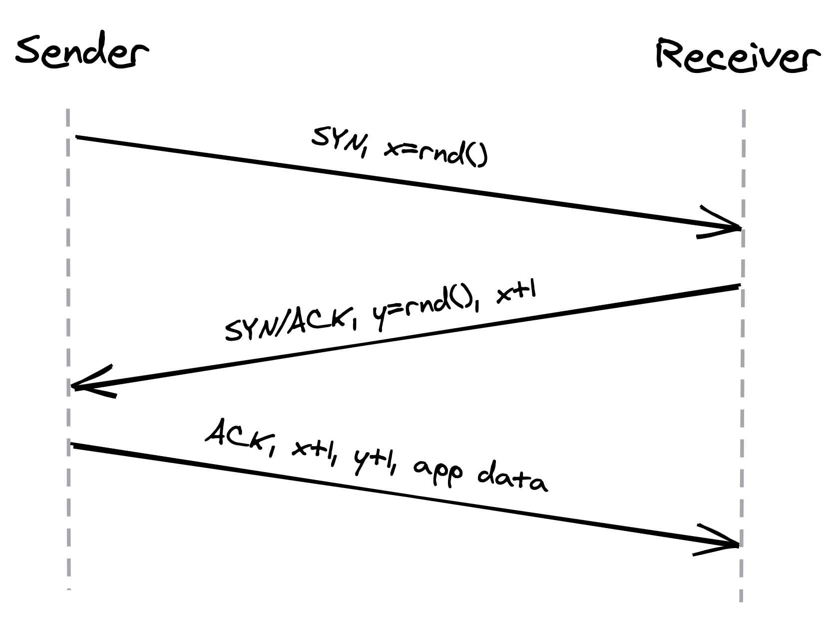
Figure 2.1: Three-way handshake
The handshake introduces a full round-trip in which no application data is sent. Until the connection has been opened, its bandwidth is essentially zero. The lower the round trip time is, the faster the connection can be established. Putting servers closer to the clients and reusing connections helps reduce this cold-start penalty.
After data transmission is complete, the connection needs to be closed to release all resources on both ends. This termination phase involves multiple round-trips.
2.3 Flow control
Flow control is a backoff mechanism implemented to prevent the sender from overwhelming the receiver. The receiver stores incoming TCP segments waiting to be processed by the process into a receive buffer, as shown in Figure 2.2.
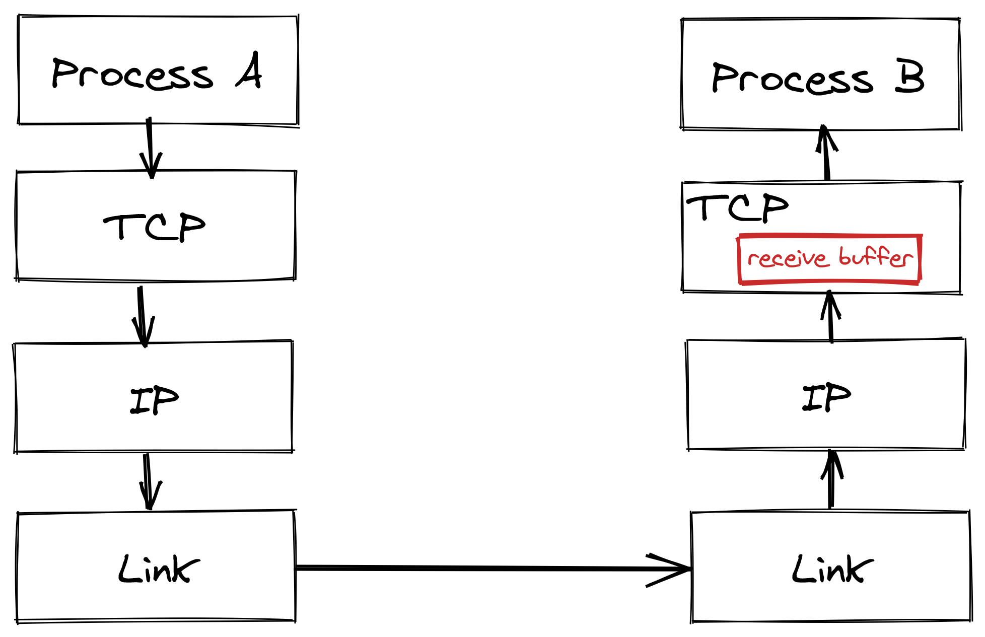
Figure 2.2: The receive buffer stores data that hasn’t been processed yet by the application.
The receiver also communicates back to the sender the size of the buffer whenever it acknowledges a segment, as shown in Figure 2.3. The sender, if it’s respecting the protocol, avoids sending more data that can fit in the receiver’s buffer.
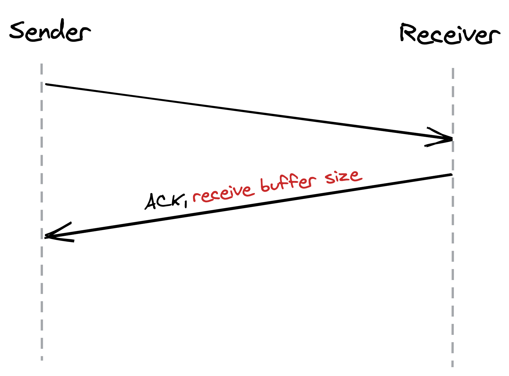
Figure 2.3: The size of the receive buffer is communicated in the headers of acknowledgments segments.
This mechanism is not too dissimilar to rate-limiting at the service level. But, rather than rate-limiting on an API key or IP address, TCP is rate-limiting on a connection level.
2.4 Congestion control
TCP not only guards against overwhelming the receiver, but also against flooding the underlying network.
The sender estimates the available bandwidth of the underlying network empirically through measurements. The sender maintains a so-called congestion window, which represents the total number of outstanding segments that can be sent without an acknowledgment from the other side. The size of the receiver window limits the maximum size of the congestion window. The smaller the congestion window is, the fewer bytes can be in-flight at any given time, and the less bandwidth is utilized.
When a new connection is established, the size of the congestion window is set to a system default. Then, for every segment acknowledged, the window increases its size exponentially until reaching an upper limit. This means that we can’t use the network’s full capacity right after a connection is established. The lower the round trip time (RTT) is, the quicker the sender can start utilizing the underlying network’s bandwidth, as shown in Figure 2.4.
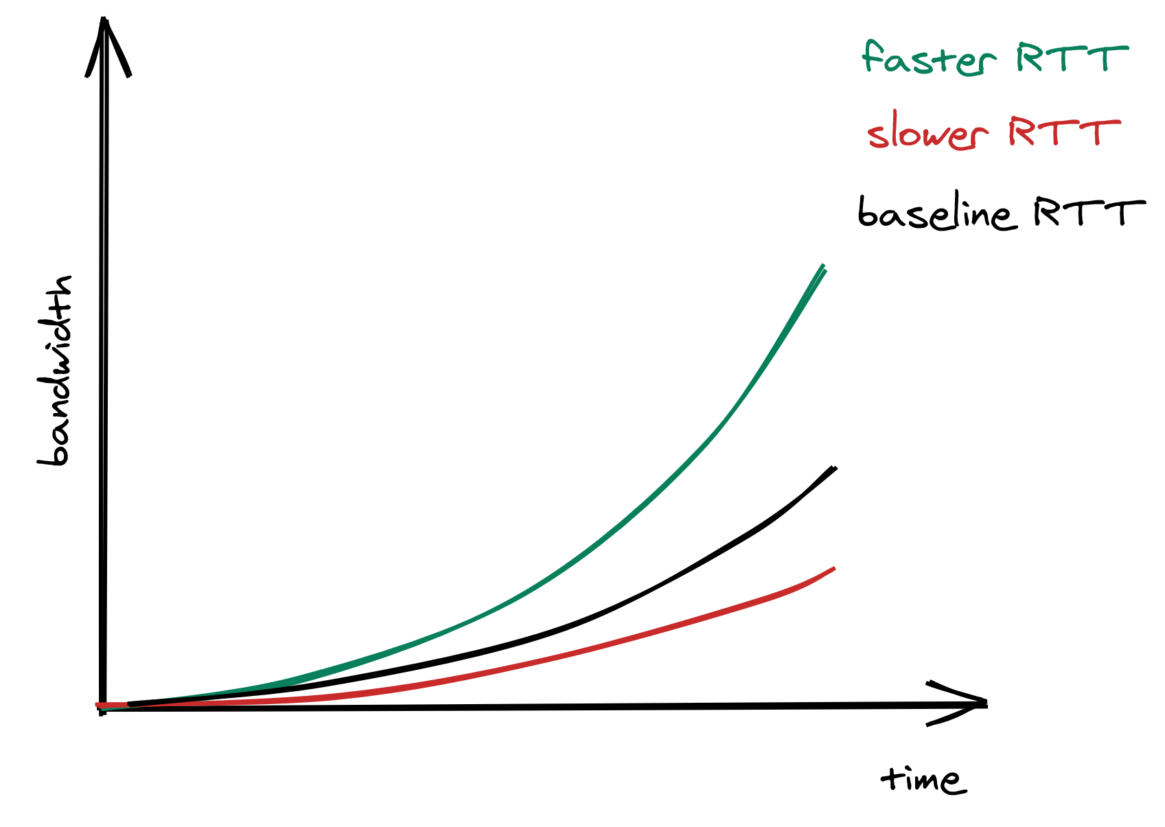
Figure 2.4: The lower the RTT is, the quicker the sender can start utilizing the underlying network’s bandwidth.
What happens if a segment is lost? When the sender detects a missed acknowledgment through a timeout, a mechanism called congestion avoidance kicks in, and the congestion window size is reduced. From there onwards, the passing of time increases the window size by a certain amount, and timeouts decrease it by another.
As mentioned earlier, the size of the congestion window defines the maximum number of bytes that can be sent without receiving an acknowledgment. Because the sender needs to wait for a full round trip to get an acknowledgment, we can derive the maximum theoretical bandwidth by dividing the size of the congestion window by the round trip time:
The equation shows that bandwidth is a function of latency. TCP will try very hard to optimize the window size since it can’t do anything about the round trip time. However, that doesn’t always yield the optimal configuration. Due to the way congestion control works, the lower the round trip time is, the better the underlying network’s bandwidth is utilized. This is more reason to put servers geographically close to the clients.
2.5 Custom protocols
TCP’s reliability and stability come at the price of lower bandwidth and higher latencies than the underlying network is actually capable of delivering. If you drop the stability and reliability mechanisms that TCP provides, what you get is a simple protocol named User Datagram Protocol (UDP) — a connectionless transport layer protocol that can be used as an alternative to TCP.
Unlike TCP, UDP does not expose the abstraction of a byte stream to its clients. Clients can only send discrete packets, called datagrams, with a limited size. UDP doesn’t offer any reliability as datagrams don’t have sequence numbers and are not acknowledged. UDP doesn’t implement flow and congestion control either. Overall, UDP is a lean and barebone protocol. It’s used to bootstrap custom protocols, which provide some, but not all, of the stability and reliability guarantees that TCP does1.
For example, in modern multi-player games, clients sample gamepad, mouse and keyboard events several times per second and send them to a server that keeps track of the global game state. Similarly, the server samples the game state several times per second and sends these snapshots back to the clients. If a snapshot is lost in transmission, there is no value in retransmitting it as the game evolves in real-time; by the time the retransmitted snapshot would get to the destination, it would be obsolete. This is a use case where UDP shines, as TCP would attempt to redeliver the missing data and consequently slow down the client’s experience.