Chapter 14
Component Diagrams
A debate that’s always ranged large in the OO community is what the difference is between a component and any regular class. This is not a debate that I want to settle here, but I can show you the notation the UML uses to distinguish between them.
UML 1 had a distinctive symbol for a component (Figure 14.1). UML 2 removed that icon but allows you to annotate a class box with a similar-looking icon. Alternatively, you can use the «component» keyword.
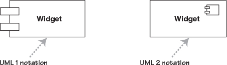
Other than the icon, components don’t introduce any notation that we haven’t already seen. Components are connected through implemented and required interfaces and often use the notations from Composite Structures that we saw in Chapter 13.
Figure 14.2 shows an example component diagram. In this example sales tills connect to the sales servers component using a sales message interface via a message queue. The queue supplies both the sales message interface to talk with the till and requires that interface to talk with the server. The server is broken down into two major components: the transaction processor realizes the sales message interface and the accounting driver talks to the accounting system.
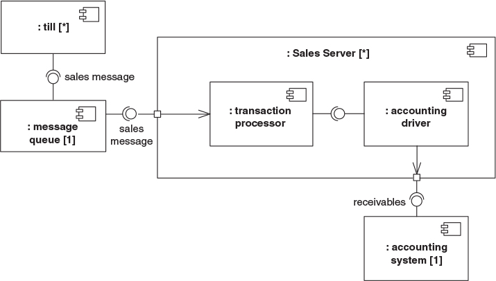
In all cases these components are shown as parts of a wider retail system, hence the leading colons. Multiplicity markers indicate that there are many tills and servers, but only one queue and accounting system. If you don’t show a multiplicity, as I haven’t for the internals of the sales server, it’s assumed to be one. In general I prefer to explicitly show the multiplicity if it’s of any importance. You can use either the ball-and-socket notation or simple lines for the connectors. The ball and socket is useful to show an interface, otherwise a simple line is easier to draw.
Figure 14.2 is in the style of a Composite Structure Diagram. Indeed I think of it as the same as a Composite Structure Diagram, but with a minor adornment that makes the parts components. You can also draw Component Diagrams in the form of class diagrams—usually these focus on the dependencies between the components. A good way to think of this is that component class diagrams show the possible connection between components, while the component composite structure shows the actual connections between components in a specific context.
As I’ve already said, the issue of what is a component is the subject of endless debate. One of the more helpful statements I’ve found is this:
Components are not a technology. Technology people seem to find this hard to understand. Components are about how customers want to relate to software. They want to be able to buy their software a piece at a time, and to be able to upgrade it just like they can upgrade their stereo. They want new pieces to work seamlessly with their old pieces, and to be able to upgrade on their own schedule, not the manufacturer’s schedule. They want to be able to mix and match pieces from various manufacturers. This is a very reasonable requirement. It is just hard to satisfy.
Ralph Johnson, http://www.c2.com/cgi/wiki?DoComponentsExist
The important point is that components represent pieces that are independently purchasable and upgradeable. As a result, dividing a system into components is as much a marketing decision as it is a technical decision, for which [Hohmann] is an excellent guide. It’s also a reminder to beware of overly fine-grained components, because too many components are hard to manage, especially when versioning rears its ugly head, hence “DLL hell.”
In earlier versions of the UML, components were used to represent physical structures, such as DLLs. That’s no longer true; for this task, you now use artifacts (page 97).
When to Use Component Diagrams
Use component diagrams when you are dividing your system into components and want to show their interrelationships through interfaces or the breakdown of components into a lower-level structure.