Homework Problems and Questions
Chapter 9 Review Questions
SECTION 9.1
R1. Reconstruct Table 9.1 for when Victor Video is watching a 4 Mbps video, Facebook Frank is looking at a new 100 Kbyte image every 20 seconds, and Martha Music is listening to 200 kbps audio stream.
R2. There are two types of redundancy in video. Describe them, and discuss how they can be exploited for efficient compression.
R3. Suppose an analog audio signal is sampled 16,000 times per second, and each sample is quantized into one of 1024 levels. What would be the resulting bit rate of the PCM digital audio signal?
R4. Multimedia applications can be classified into three categories. Name and describe each category.
SECTION 9.2
R5. Streaming video systems can be classified into three categories. Name and briefly describe each of these categories.
R6. List three disadvantages of UDP streaming.
R7. With HTTP streaming, are the TCP receive buffer and the client’s application buffer the same thing? If not, how do they interact?
R8. Consider the simple model for HTTP streaming. Suppose the server sends bits at a constant rate of 2 Mbps and playback begins when 8 million bits have been received. What is the initial buffering delay tp?
SECTION 9.3
R9. What is the difference between end-to-end delay and packet jitter? What are the causes of packet jitter?
R10. Why is a packet that is received after its scheduled playout time considered lost?
R11. Section 9.3 describes two FEC schemes. Briefly summarize them. Both schemes increase the transmission rate of the stream by adding overhead. Does interleaving also increase the transmission rate?
SECTION 9.4
R12. How are different RTP streams in different sessions identified by a receiver? How are different streams from within the same session identified?
R13. What is the role of a SIP registrar? How is the role of an SIP registrar different from that of a home agent in Mobile IP?
Problems
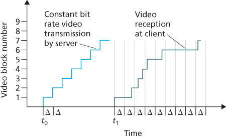
P1. Consider the figure below. Similar to our discussion of Figure 9.1 , suppose that video is encoded at a fixed bit rate, and thus each video block contains video frames that are to be played out over the same fixed amount of time, Δ. The server transmits the first video block at t0, the second block at
Description
In this graph, the x-axis is labeled "Time" and the y-axis is labeled "Video block number." The y-axis omits 0 but moves upwards in increments of one to 9. In the left half of the x-axis we see a blue line rising upwards to the right in a stair-step fashion. This line is labeled "Constant bit rate video transmission by server." It begins at a point labeled "t0." The line rises to 1 on the y-axis then extends horizontally to the right for one unit defined as Delta. It then goes up to 2 and over one Delta, etc. until it reaches 7 on the y-axis.
In the right half of the x-axis we see a dark blue line, labeled "Video reception at client," rise from a point labeled t1 and extend upward to the right in an inconsistent fashion. The x-axis is delineated from this point into units of Delta. This line rises to 1 on the y-axis and then extends horizontally for one and a half Deltas. It rises to 2 and extends into the next Delta. Then it rises to 3 and extends within the same Delta, then rises to 4 and extends just barely into the next Delta. From here it rises to 5 and extends through the Delta and halfway into the next Delta. From here it rises to 6 and extends three Deltas, then rises to seven.
Suppose that the client begins playout as soon as the first block arrives at t1. In the figure below, how many blocks of video (including the first block) will have arrived at the client in time for their playout? Explain how you arrived at your answer.
Suppose that the client begins playout now at
In the same scenario at (b) above, what is the largest number of blocks that is ever stored in the client buffer, awaiting playout? Explain how you arrived at your answer.
What is the smallest playout delay at the client, such that every video block has arrived in time for its playout? Explain how you arrived at your answer.
P2. Recall the simple model for HTTP streaming shown in Figure 9.3 . Recall that B denotes the size of the client’s application buffer, and Q denotes the number of bits that must be buffered before the client application begins playout. Also r denotes the video consumption rate. Assume that the server sends bits at a constant rate x whenever the client buffer is not full.
Suppose that
Now suppose that
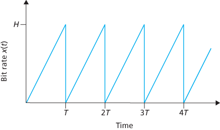
P3. Recall the simple model for HTTP streaming shown in Figure 9.3 . Suppose the buffer size is infinite but the server sends bits at variable rate x(t). Specifically, suppose x(t) has the following saw-tooth shape. The rate is initially zero at time
Description
In this graph, the x-axis is labeled "Time" and the y-axis is labeled "Bit rate x(t)." The x-axis is divided at regular intervals into T, 2T, 3T, and 4T. The y-axis is unmarked except for an H near its top.
A blue line begins at the intersection of x and y and rises sharply to H on the y-axis at T on the x-axis, then drops vertically to the x-axis. From here it rises sharply to H on the y-axis and 2T on the x-axis, then drops vertically to the x-axis. This pattern is repeated twice more.
What is the server’s average send rate?
Suppose that
Now suppose
Suppose
Suppose
Now suppose that the buffer size B is finite. Suppose
P4. Recall the simple model for HTTP streaming shown in Figure 9.3 . Suppose the client application buffer is infinite, the server sends at the constant rate x, and the video consumption rate is r with
Suppose the video is infinitely long. How many bits are wasted (that is, sent but not viewed)?
Suppose the video is T seconds long with
P5. Consider a DASH system (as discussed in Section 2.6 ) for which there are N video versions (at N different rates and qualities) and N audio versions (at N different rates and qualities). Suppose we want to allow the player to choose at any time any of the N video versions and any of the N audio versions.
If we create files so that the audio is mixed in with the video, so server sends only one media stream at given time, how many files will the server need to store (each a different URL)?
If the server instead sends the audio and video streams separately and has the client synchronize the streams, how many files will the server need to store?
P6. In the VoIP example in Section 9.3 , let h be the total number of header bytes added to each chunk, including UDP and IP header.
Assuming an IP datagram is emitted every 20 msecs, find the transmission rate in bits per second for the datagrams generated by one side of this application.
What is a typical value of h when RTP is used?
P7. Consider the procedure described in Section 9.3 for estimating average delay di. Suppose that
For a given audio application suppose four packets have arrived at the receiver with sample delays
Generalize your formula for n sample delays.
For the formula in part (b), let n approach infinity and give the resulting formula. Comment on why this averaging procedure is called an exponential moving average.
P8. Repeat parts (a) and (b) in Question P7 for the estimate of average delay deviation.
P9. For the VoIP example in Section 9.3 , we introduced an online procedure (exponential moving average) for estimating delay. In this problem we will examine an alternative procedure. Let ti be the timestamp of the ith packet received; let ri be the time at which the ith packet is received. Let dn be our estimate of average delay after receiving the nth packet. After the first packet is received, we set the delay estimate equal to
Suppose that we would like
Describe why for Internet telephony, the delay estimate described in Section 9.3 is more appropriate than the delay estimate outlined in part (a).
P10. Compare the procedure described in Section 9.3 for estimating average delay with the procedure in Section 3.5 for estimating round-trip time. What do the procedures have in common? How are they different?
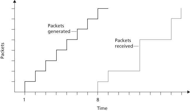
P11. Consider the figure below (which is similar to Figure 9.3 ). A sender begins sending packetized audio periodically at
Description
In this graph, the x-axis is labeled "Time" and the y-axis is labeled "Packets." The x-axis begins at 0 and moves at regular intervals in increments of one to sixteen. Only 1 and 8 are actually numbered. The y-axis is also is notched at eight regular intervals, though these are not labeled.
At 1 on the x-axis, a line extends upwards to the right in a stair-step fashion. It rises to 1 on the y-axis then over to 2 on the x-axis, then up to 2 on y and 3 on x, etc. to the top of the graph. This line is labeled "Packets generated."
At 8 on the x-axis, a line extends upwards to the right in an inconsistent stair-step fashion. It rises to 1 on the y-axis then extends horizontally over to 9 on the x-axis. From there it rises to 2 on the y-axis and extends to 12 on the x-axis. From there it rises to 5 on the y-axis and extends to 15 on the x-axis. From there it rises to 7 on the y-axis and extends to 16 on the x-axis, then rises to 8 on the y-axis
What are the delays (from sender to receiver, ignoring any playout delays) of packets 2 through 8? Note that each vertical and horizontal line segment in the figure has a length of 1, 2, or 3 time units.
If audio playout begins as soon as the first packet arrives at the receiver at
If audio playout begins at
What is the minimum playout delay at the receiver that results in all of the first eight packets arriving in time for their playout?
P12. Consider again the figure in P11, showing packet audio transmission and reception times.
Compute the estimated delay for packets 2 through 8, using the formula for di from Section 9.3.2 . Use a value of
Compute the estimated deviation of the delay from the estimated average for packets 2 through 8, using the formula for vi from Section 9.3.2 . Use a value of
P13. Recall the two FEC schemes for VoIP described in Section 9.3 . Suppose the first scheme generates a redundant chunk for every four original chunks. Suppose the second scheme uses a low-bit rate encoding whose transmission rate is 25 percent of the transmission rate of the nominal stream.
How much additional bandwidth does each scheme require? How much playback delay does each scheme add?
How do the two schemes perform if the first packet is lost in every group of five packets? Which scheme will have better audio quality?
How do the two schemes perform if the first packet is lost in every group of two packets? Which scheme will have better audio quality?
P14.
Consider an audio conference call in Skype with
Repeat part (a) for a Skype video conference call using a central server.
Repeat part (b), but now for when each peer sends a copy of its video stream to each of the
P15.
Suppose we send into the Internet two IP datagrams, each carrying a different UDP segment. The first datagram has source IP address A1, destination IP address B, source port P1, and destination port T. The second datagram has source IP address A2, destination IP address B, source port P2, and destination port T. Suppose that A1 is different from A2 and that P1 is different from P2. Assuming that both datagrams reach their final destination, will the two UDP datagrams be received by the same socket? Why or why not?
Suppose Alice, Bob, and Claire want to have an audio conference call using SIP and RTP. For Alice to send and receive RTP packets to and from Bob and Claire, is only one UDP socket sufficient (in addition to the socket needed for the SIP messages)? If yes, then how does Alice’s SIP client distinguish between the RTP packets received from Bob and Claire?
P16. True or false:
If stored video is streamed directly from a Web server to a media player, then the application is using TCP as the underlying transport protocol.
When using RTP, it is possible for a sender to change encoding in the middle of a session.
All applications that use RTP must use port 87.
If an RTP session has a separate audio and video stream for each sender, then the audio and video streams use the same SSRC.
In differentiated services, while per-hop behavior defines differences in performance among classes, it does not mandate any particular mechanism for achieving these performances.
Description
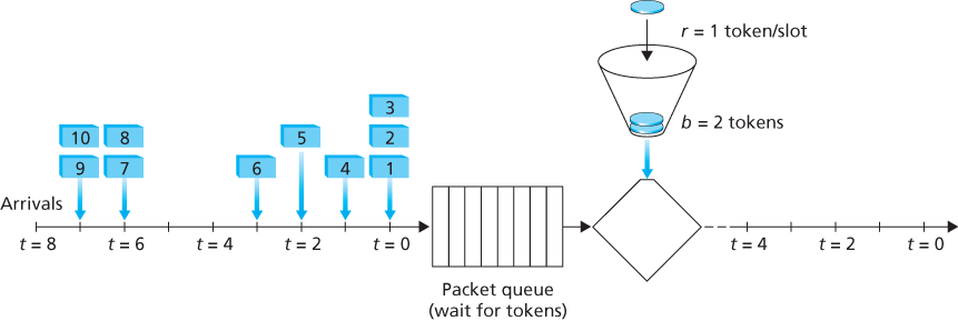
In this illustration, we see (from left to right) a horizontal line labeled "Arrivals," which is marked at regular intervals and labeled at every other mark. The first mark is labeled "t =8," then "t = 6," and so on to "t = 0." At t = 7 we see two data packets labeled 10 and 9. At t = 6 we see two data packets labeled 8 and 7. At t = 3 we see one data packet labeled 6. At t = 2 we see one data packet labeled 5. At t = 1 we see one data packet labeled 4. And at t = 0 we see three data packets labeled 3, 2, and 1.
To the right of the arrivals we see "Packet queue (wait for tokens)" with eight empty slots. To the right of the packet queue is the "remove token" diamond shape from figure 9.14 (though unlabeled here). Above it is the leaky bucket, with the dropped token labeled "r = 1 token/slot," and the bucket labeled "b = 2 tokens."
To the right of the diamond is a horizontal line pointing to the right and notched at regular intervals and labeled at every other notch, beginning with "t = 4" and ending with "t = 0."
Suppose Alice wants to establish an SIP session with Bob. In her INVITE message she includes the line: m=audio 48753 RTP/AVP 3 (AVP 3 denotes GSM audio). Alice has therefore indicated in this message that she wishes to send GSM audio.
Referring to the preceding statement, Alice has indicated in her INVITE message that she will send audio to port 48753.
SIP messages are typically sent between SIP entities using a default SIP port number.
In order to maintain registration, SIP clients must periodically send REGISTER messages.
SIP mandates that all SIP clients support G.711 audio encoding.
P17. Consider the figure below, which shows a leaky bucket policer being fed by a stream of packets. The token buffer can hold at most two tokens, and is initially full at
Packets (if any) arrive at the beginning of the slot. Thus in the figure, packets 1, 2, and 3 arrive in slot 0. If there are already packets in the queue, then the arriving packets join the end of the queue. Packets proceed towards the front of the queue in a FIFO manner.
After the arrivals have been added to the queue, if there are any queued packets, one or two of those packets (depending on the number of available tokens) will each remove a token from the token buffer and go to the output link during that slot. Thus, packets 1 and 2 each remove a token from the buffer (since there are initially two tokens) and go to the output link during slot 0.
A new token is added to the token buffer if it is not full, since the token generation rate is r = 1 token/slot.
Time then advances to the next time slot, and these steps repeat.
Answer the following questions:
For each time slot, identify the packets that are in the queue and the number of tokens in the bucket, immediately after the arrivals have been processed (step 1 above) but before any of the packets have passed through the queue and removed a token. Thus, for the
For each time slot indicate which packets appear on the output after the token(s) have been removed from the queue. Thus, for the
P18. Repeat P17 but assume that
P19. Consider P18 and suppose now that
P20. Consider the leaky bucket policer that polices the average rate and burst size of a packet flow. We now want to police the peak rate, p, as well. Show how the output of this leaky bucket policer can be fed into a second leaky bucket policer so that the two leaky buckets in series police the average rate, peak rate, and burst size. Be sure to give the bucket size and token generation rate for the second policer.
P21. A packet flow is said to conform to a leaky bucket specification (r, b) with burst size b and average rate r if the number of packets that arrive to the leaky bucket is less than
P22. Show that as long as
Programming Assignment
In this lab, you will implement a streaming video server and client. The client will use the real-time streaming protocol (RTSP) to control the actions of the server. The server will use the real-time protocol (RTP) to packetize the video for transport over UDP. You will be given Python code that partially implements RTSP and RTP at the client and server. Your job will be to complete both the client and server code. When you are finished, you will have created a client-server application that does the following:
The client sends SETUP, PLAY, PAUSE, and TEARDOWN RTSP commands, and the server responds to the commands.
When the server is in the playing state, it periodically grabs a stored JPEG frame, packetizes the frame with RTP, and sends the RTP packet into a UDP socket.
The client receives the RTP packets, removes the JPEG frames, decompresses the frames, and renders the frames on the client’s monitor.
The code you will be given implements the RTSP protocol in the server and the RTP depacketization in the client. The code also takes care of displaying the transmitted video. You will need to implement RTSP in the client and RTP server. This programming assignment will significantly enhance the student’s understanding of RTP, RTSP, and streaming video. It is highly recommended. The assignment also suggests a number of optional exercises, including implementing the RTSP DESCRIBE command at both client and server. You can find full details of the assignment, as well as an overview of the RTSP protocol, at the Web site www.pearsonhighered.com/