9.5 Network Support for Multimedia
In Sections 9.2 through 9.4, we learned how application-level mechanisms such as client buffering, prefetching, adapting media quality to available bandwidth, adaptive playout, and loss mitigation techniques can be used by multimedia applications to improve a multimedia application’s performance. We also learned how content distribution networks and P2P overlay networks can be used to provide a system-level approach for delivering multimedia content. These techniques and approaches are all designed to be used in today’s best-effort Internet. Indeed, they are in use today precisely because the Internet provides only a single, best-effort class of service. But as designers of computer networks, we can’t help but ask whether the network (rather than the applications or application-level infrastructure alone) might provide mechanisms to support multimedia content delivery. As we’ll see shortly, the answer is, of course, “yes”! But we’ll also see that a number of these new network-level mechanisms have yet to be widely deployed. This may be due to their complexity and to the fact that application-level techniques together with best-effort service and properly dimensioned network resources (for example, bandwidth) can indeed provide a “good-enough” (even if not-always-perfect) end-to-end multimedia delivery service.
Table 9.4 summarizes three broad approaches towards providing network-level support for multimedia applications.
Making the best of best-effort service. The application-level mechanisms and infrastructure that we studied in Sections 9.2 through 9.4 can be successfully used in a well-dimensioned network where packet loss and excessive end-to-end delay rarely occur. When demand increases are forecasted, the ISPs deploy additional bandwidth and switching capacity to continue to ensure satisfactory delay and packet-loss performance [Huang 2005]. We’ll discuss such network dimensioning further in Section 9.5.1.
Differentiated service. Since the early days of the Internet, it’s been envisioned that different types of traffic (for example, as indicated in the Type-of-Service field in the IP4v packet header) could be provided with different classes of service, rather than a single one-size-fits-all best-effort service. With differentiated service, one type of traffic might be given strict priority over another class of traffic when both types of traffic are queued at a router. For example, packets belonging to a real-time conversational application might be given priority over other packets due to their stringent delay constraints. Introducing differentiated service into the network will require new mechanisms for packet marking (indicating a packet’s class of service), packet scheduling, and more. We’ll cover differentiated service, and new network mechanisms needed to implement this service, in Sections 9.5.2 and 9.5.3.
Table 9.4 Three network-level approaches to supporting multimedia applications
Approach Granularity Guarantee Mechanisms Complexity Deployment to date Making the best of best-effort service all traffic treated equally none, or soft application-layer support, CDNs, overlays, network-level resource provisioning minimal everywhere Differentiated service different classes of traffic treated differently none, or soft packet marking, policing, scheduling medium some Per-connection Quality-of-Service (QoS) Guarantees each source-destination flows treated differently soft or hard, once flow is admitted packet marking, policing, scheduling; call admission and signaling light little Per-connection Quality-of-Service (QoS) Guarantees. With per-connection QoS guarantees, each instance of an application explicitly reserves end-to-end bandwidth and thus has a guaranteed end-to-end performance. A hard guarantee means the application will receive its requested quality of service (QoS) with certainty. A soft guarantee means the application will receive its requested quality of service with high probability. For example, if a user wants to make a VoIP call from Host A to Host B, the user’s VoIP application reserves bandwidth explicitly in each link along a route between the two hosts. But permitting applications to make reservations and requiring the network to honor the reservations requires some big changes. First, we need a protocol that, on behalf of the applications, reserves link bandwidth on the paths from the senders to their receivers. Second, we’ll need new scheduling policies in the router queues so that per-connection bandwidth reservations can be honored. Finally, in order to make a reservation, the applications must give the network a description of the traffic that they intend to send into the network and the network will need to police each application’s traffic to make sure that it abides by that description. These mechanisms, when combined, require new and complex software in hosts and routers. Because per-connection QoS guaranteed service has not seen significant deployment, we’ll cover these mechanisms only briefly in Section 9.5.4.
9.5.1 Dimensioning Best-Effort Networks
Fundamentally, the difficulty in supporting multimedia applications arises from their stringent performance requirements—low end-to-end packet delay, delay jitter, and loss—and the fact that packet delay, delay jitter, and loss occur whenever the network becomes congested. A first approach to improving the quality of multimedia applications—an approach that can often be used to solve just about any problem where resources are constrained—is simply to “throw money at the problem” and thus simply avoid resource contention. In the case of networked multimedia, this means providing enough link capacity throughout the network so that network congestion, and its consequent packet delay and loss, never (or only very rarely) occurs. With enough link capacity, packets could zip through today’s Internet without queuing delay or loss. From many perspectives this is an ideal situation—multimedia applications would perform perfectly, users would be happy, and this could all be achieved with no changes to Internet’s best-effort architecture.
The question, of course, is how much capacity is “enough” to achieve this nirvana, and whether the costs of providing “enough” bandwidth are practical from a business standpoint to the ISPs. The question of how much capacity to provide at network links in a given topology to achieve a given level of performance is often known as bandwidth provisioning. The even more complicated problem of how to design a network topology (where to place routers, how to interconnect routers with links, and what capacity to assign to links) to achieve a given level of end-to-end performance is a network design problem often referred to as network dimensioning. Both bandwidth provisioning and network dimensioning are complex topics, well beyond the scope of this textbook. We note here, however, that the following issues must be addressed in order to predict application-level performance between two network end points, and thus provision enough capacity to meet an application’s performance requirements.
Models of traffic demand between network end points. Models may need to be specified at both the call level (for example, users “arriving” to the network and starting up end-to-end applications) and at the packet level (for example, packets being generated by ongoing applications). Note that workload may change over time.
Well-defined performance requirements. For example, a performance requirement for supporting delay-sensitive traffic, such as a conversational multimedia application, might be that the probability that the end-to-end delay of the packet is greater than a maximum tolerable delay be less than some small value [Fraleigh 2003].
Models to predict end-to-end performance for a given workload model, and techniques to find a minimal cost bandwidth allocation that will result in all user requirements being met. Here, researchers are busy developing performance models that can quantify performance for a given workload, and optimization techniques to find minimal-cost bandwidth allocations meeting performance requirements.
Given that today’s best-effort Internet could (from a technology standpoint) support multimedia traffic at an appropriate performance level if it were dimensioned to do so, the natural question is why today’s Internet doesn’t do so. The answers are primarily economic and organizational. From an economic standpoint, would users be willing to pay their ISPs enough for the ISPs to install sufficient bandwidth to support multimedia applications over a best-effort Internet? The organizational issues are perhaps even more daunting. Note that an end-to-end path between two multimedia end points will pass through the networks of multiple ISPs. From an organizational standpoint, would these ISPs be willing to cooperate (perhaps with revenue sharing) to ensure that the end-to-end path is properly dimensioned to support multimedia applications? For a perspective on these economic and organizational issues, see [Davies 2005]. For a perspective on provisioning tier-1 backbone networks to support delay-sensitive traffic, see [Fraleigh 2003].
9.5.2 Providing Multiple Classes of Service
Perhaps the simplest enhancement to the one-size-fits-all best-effort service in today’s Internet is to divide traffic into classes, and provide different levels of service to these different classes of traffic. For example, an ISP might well want to provide a higher class of service to delay-sensitive Voice-over-IP or teleconferencing traffic (and charge more for this service!) than to elastic traffic such as e-mail or HTTP. Alternatively, an ISP may simply want to provide a higher quality of service to customers willing to pay more for this improved service. A number of residential wired-access ISPs and cellular wireless-access ISPs have adopted such tiered levels of service—with platinum-service subscribers receiving better performance than gold- or silver-service subscribers.
We’re all familiar with different classes of service from our everyday lives—first-class airline passengers get better service than business-class passengers, who in turn get better service than those of us who fly economy class; VIPs are provided immediate entry to events while everyone else waits in line; elders are revered in some countries and provided seats of honor and the finest food at a table. It’s important to note that such differential service is provided among aggregates of traffic, that is, among classes of traffic, not among individual connections. For example, all first-class passengers are handled the same (with no first-class passenger receiving any better treatment than any other first-class passenger), just as all VoIP packets would receive the same treatment within the network, independent of the particular end-to-end connection to which they belong. As we will see, by dealing with a small number of traffic aggregates, rather than a large number of individual connections, the new network mechanisms required to provide better-than-best service can be kept relatively simple.
The early Internet designers clearly had this notion of multiple classes of service in mind. Recall the type-of-service (ToS) field in the IPv4 header discussed in Chapter 4. IEN123 [ISI 1979] describes the ToS field also present in an ancestor of the IPv4 datagram as follows: “The Type of Service [field] provides an indication of the abstract parameters of the quality of service desired. These parameters are to be used to guide the selection of the actual service parameters when transmitting a datagram through a particular network. Several networks offer service precedence, which somehow treats high precedence traffic as more important that other traffic.” More than four decades ago, the vision of providing different levels of service to different classes of traffic was clear! However, it’s taken us an equally long period of time to realize this vision.
Motivating Scenarios
Let’s begin our discussion of network mechanisms for providing multiple classes of service with a few motivating scenarios.
Figure 9.11 shows a simple network scenario in which two application packet flows originate on Hosts H1 and H2 on one LAN and are destined for Hosts H3 and H4 on another LAN. The routers on the two LANs are connected by a 1.5 Mbps link. Let’s assume the LAN speeds are significantly higher than 1.5 Mbps, and focus on the output queue of router R1; it is here that packet delay and packet loss will occur if the aggregate sending rate of H1 and H2 exceeds 1.5 Mbps. Let’s further suppose that a 1 Mbps audio application (for example, a CD-quality audio call) shares the
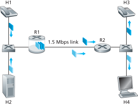
Figure 9.11 Competing audio and HTTP applications
1.5 Mbps link between R1 and R2 with an HTTP Web-browsing application that is downloading a Web page from H2 to H4.
In the best-effort Internet, the audio and HTTP packets are mixed in the output queue at R1 and (typically) transmitted in a first-in-first-out (FIFO) order. In this scenario, a burst of packets from the Web server could potentially fill up the queue, causing IP audio packets to be excessively delayed or lost due to buffer overflow at R1. How should we solve this potential problem? Given that the HTTP Web-browsing application does not have time constraints, our intuition might be to give strict priority to audio packets at R1. Under a strict priority scheduling discipline, an audio packet in the R1 output buffer would always be transmitted before any HTTP packet in the R1 output buffer. The link from R1 to R2 would look like a dedicated link of 1.5 Mbps to the audio traffic, with HTTP traffic using the R1-to-R2 link only when no audio traffic is queued. In order for R1 to distinguish between the audio and HTTP packets in its queue, each packet must be marked as belonging to one of these two classes of traffic. This was the original goal of the type-of-service (ToS) field in IPv4. As obvious as this might seem, this then is our first insight into mechanisms needed to provide multiple classes of traffic:
Insight 1: Packet marking allows a router to distinguish among packets belonging to different classes of traffic.
Note that although our example considers a competing multimedia and elastic flow, the same insight applies to the case that platinum, gold, and silver classes of service are implemented—a packet-marking mechanism is still needed to indicate that class of service to which a packet belongs.
Now suppose that the router is configured to give priority to packets marked as belonging to the 1 Mbps audio application. Since the outgoing link speed is 1.5 Mbps, even though the HTTP packets receive lower priority, they can still, on average, receive 0.5 Mbps of transmission service. But what happens if the audio application starts sending packets at a rate of 1.5 Mbps or higher (either maliciously or due to an error in the application)? In this case, the HTTP packets will starve, that is, they will not receive any service on the R1-to-R2 link. Similar problems would occur if multiple applications (for example, multiple audio calls), all with the same class of service as the audio application, were sharing the link’s bandwidth; they too could collectively starve the FTP session. Ideally, one wants a degree of isolation among classes of traffic so that one class of traffic can be protected from the other. This protection could be implemented at different places in the network—at each and every router, at first entry to the network, or at inter-domain network boundaries. This then is our second insight:
Insight 2: It is desirable to provide a degree of traffic isolation among classes so that one class is not adversely affected by another class of traffic that misbehaves.
We’ll examine several specific mechanisms for providing such isolation among traffic classes. We note here that two broad approaches can be taken. First, it is possible to perform traffic policing, as shown in Figure 9.12. If a traffic class or flow must meet certain criteria (for example, that the audio flow not exceed a peak rate of 1 Mbps), then a policing mechanism can be put into place to ensure that these criteria are indeed observed. If the policed application misbehaves, the policing mechanism will take some action (for example, drop or delay packets that are in violation of the criteria) so that the traffic actually entering the network conforms to the criteria. The leaky bucket mechanism that we’ll examine shortly is perhaps the most widely used policing mechanism. In Figure 9.12, the packet classification and marking mechanism (Insight 1) and the policing mechanism (Insight 2) are both implemented together at the network’s edge, either in the end system or at an edge router.
A complementary approach for providing isolation among traffic classes is for the link-level packet-scheduling mechanism to explicitly allocate a fixed amount of link bandwidth to each class. For example, the audio class could be allocated 1 Mbps at R1, and the HTTP class could be allocated 0.5 Mbps. In this case, the audio and
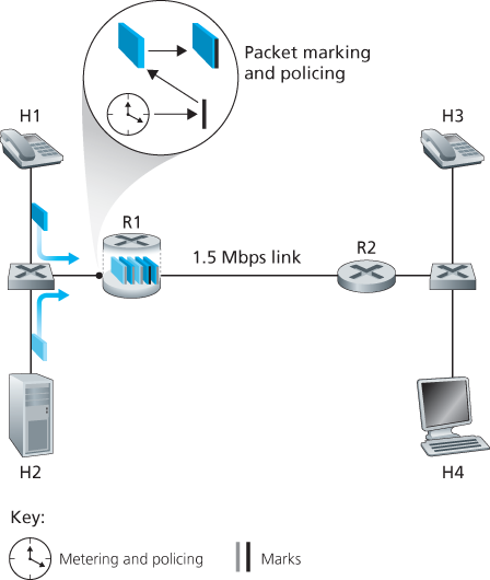
Figure 9.12 Policing (and marking) the audio and HTTP traffic classes
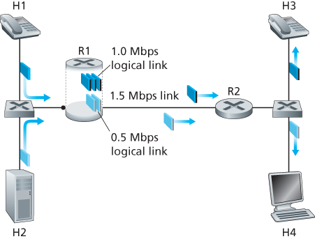
Figure 9.13 Logical isolation of audio and HTTP traffic classes
HTTP flows see a logical link with capacity 1.0 and 0.5 Mbps, respectively, as shown in Figure 9.13. With strict enforcement of the link-level allocation of bandwidth, a class can use only the amount of bandwidth that has been allocated; in particular, it cannot utilize bandwidth that is not currently being used by others. For example, if the audio flow goes silent (for example, if the speaker pauses and generates no audio packets), the HTTP flow would still not be able to transmit more than 0.5 Mbps over the R1-to-R2 link, even though the audio flow’s 1 Mbps bandwidth allocation is not being used at that moment. Since bandwidth is a “use-it-or-lose-it” resource, there is no reason to prevent HTTP traffic from using bandwidth not used by the audio traffic. We’d like to use bandwidth as efficiently as possible, never wasting it when it could be otherwise used. This gives rise to our third insight:
Insight 3: While providing isolation among classes or flows, it is desirable to use resources (for example, link bandwidth and buffers) as efficiently as possible.
Recall from our discussion in Sections 1.3 and 4.2 that packets belonging to various network flows are multiplexed and queued for transmission at the output buffers associated with a link. The manner in which queued packets are selected for transmission on the link is known as the link-scheduling discipline, and was discussed in detail in Section 4.2. Recall that in Section 4.2 three link-scheduling disciplines were discussed, namely, FIFO, priority queuing, and Weighted Fair Queuing (WFQ). We’ll see soon see that WFQ will play a particularly important role for isolating the traffic classes.
The Leaky Bucket
One of our earlier insights was that policing, the regulation of the rate at which a class or flow (we will assume the unit of policing is a flow in our discussion below) is allowed to inject packets into the network, is an important QoS mechanism. But what aspects of a flow’s packet rate should be policed? We can identify three important policing criteria, each differing from the other according to the time scale over which the packet flow is policed:
Average rate. The network may wish to limit the long-term average rate (packets per time interval) at which a flow’s packets can be sent into the network. A crucial issue here is the interval of time over which the average rate will be policed. A flow whose average rate is limited to 100 packets per second is more constrained than a source that is limited to 6,000 packets per minute, even though both have the same average rate over a long enough interval of time. For example, the latter constraint would allow a flow to send 1,000 packets in a given second-long interval of time, while the former constraint would disallow this sending behavior.
Peak rate. While the average-rate constraint limits the amount of traffic that can be sent into the network over a relatively long period of time, a peak-rate constraint limits the maximum number of packets that can be sent over a shorter period of time. Using our example above, the network may police a flow at an average rate of 6,000 packets per minute, while limiting the flow’s peak rate to 1,500 packets per second.
Burst size. The network may also wish to limit the maximum number of packets (the “burst” of packets) that can be sent into the network over an extremely short interval of time. In the limit, as the interval length approaches zero, the burst size limits the number of packets that can be instantaneously sent into the network. Even though it is physically impossible to instantaneously send multiple packets into the network (after all, every link has a physical transmission rate that cannot be exceeded!), the abstraction of a maximum burst size is a useful one.
The leaky bucket mechanism is an abstraction that can be used to characterize these policing limits. As shown in Figure 9.14, a leaky bucket consists of a bucket that can hold up to b tokens. Tokens are added to this bucket as follows. New tokens, which may potentially be added to the bucket, are always being generated at a rate of r tokens per second. (We assume here for simplicity that the unit of time is a second.) If the bucket is filled with less than b tokens when a token is generated, the newly generated token is added to the bucket; otherwise the newly generated token is ignored, and the token bucket remains full with b tokens.
Let us now consider how the leaky bucket can be used to police a packet flow. Suppose that before a packet is transmitted into the network, it must first remove a token from the token bucket. If the token bucket is empty, the packet must wait for
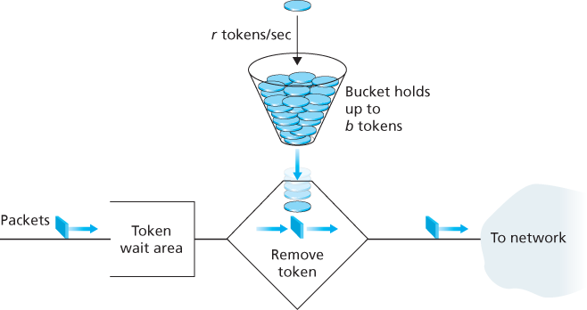
Figure 9.14 The leaky bucket policer
a token. (An alternative is for the packet to be dropped, although we will not consider that option here.) Let us now consider how this behavior polices a traffic flow. Because there can be at most b tokens in the bucket, the maximum burst size for a leaky-bucket-policed flow is b packets. Furthermore, because the token generation rate is r, the maximum number of packets that can enter the network of any interval of time of length t is
Leaky Bucket + =
Let’s close our discussion on policing by showing how the leaky bucket and WFQ can be combined to provide a bound on the delay through a router’s queue. (Readers who have forgotten about WFQ are encouraged to review WFQ, which is covered in Section 4.2.) Let’s consider a router’s output link that multiplexes n flows, each policed by a leaky bucket with parameters bi and
Recall from our discussion of WFQ that each flow, i, is guaranteed to receive a share of the link bandwidth equal to at least
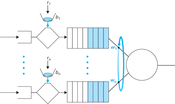
Figure 9.15 n multiplexed leaky bucket flows with WFQ scheduling
rate of the link in packets/sec. What then is the maximum delay that a packet will experience while waiting for service in the WFQ (that is, after passing through the leaky bucket)? Let us focus on flow 1. Suppose that flow 1’s token bucket is initially full. A burst of b1 packets then arrives to the leaky bucket policer for flow 1. These packets remove all of the tokens (without wait) from the leaky bucket and then join the WFQ waiting area for flow 1. Since these b1 packets are served at a rate of at least
The rationale behind this formula is that if there are b1 packets in the queue and packets are being serviced (removed) from the queue at a rate of at least
9.5.3 Diffserv
Having seen the motivation, insights, and specific mechanisms for providing multiple classes of service, let’s wrap up our study of approaches toward proving multiple classes of service with an example—the Internet Diffserv architecture [RFC 2475; Kilkki 1999]. Diffserv provides service differentiation—that is, the ability to handle different classes of traffic in different ways within the Internet in a scalable manner. The need for scalability arises from the fact that millions of simultaneous source-destination traffic flows may be present at a backbone router. We’ll see shortly that this need is met by placing only simple functionality within the network core, with more complex control operations being implemented at the network’s edge.
Let’s begin with the simple network shown in Figure 9.16. We’ll describe one possible use of Diffserv here; other variations are possible, as described in RFC 2475. The Diffserv architecture consists of two sets of functional elements:
Edge functions: Packet classification and traffic conditioning. At the incoming edge of the network (that is, at either a Diffserv-capable host that generates traffic or at the first Diffserv-capable router that the traffic passes through), arriving packets are marked. More specifically, the differentiated service (DS) field in the IPv4 or IPv6 packet header is set to some value [RFC 3260]. The definition of the DS field is intended to supersede the earlier definitions of the IPv4 type-of-service field and the IPv6 traffic class fields that we discussed in Chapter 4. For example, in Figure 9.16, packets being sent from H1 to H3 might be marked at R1, while packets being sent from H2 to H4 might be marked at R2. The mark that a packet receives identifies the class of traffic to which it belongs. Different classes of traffic will then receive different service within the core network.
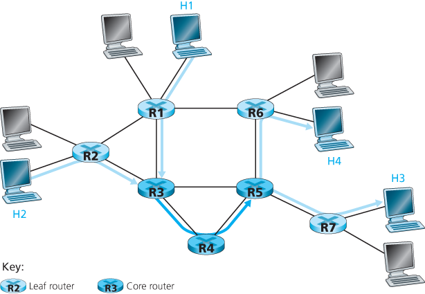
Figure 9.16 A simple Diffserv network example
Core function: Forwarding. When a DS-marked packet arrives at a Diffserv-capable router, the packet is forwarded onto its next hop according to the so-called per-hop behavior (PHB) associated with that packet’s class. The per-hop behavior influences how a router’s buffers and link bandwidth are shared among the competing classes of traffic. A crucial tenet of the Diffserv architecture is that a router’s per-hop behavior will be based only on packet markings, that is, the class of traffic to which a packet belongs. Thus, if packets being sent from H1 to H3 in Figure 9.16 receive the same marking as packets being sent from H2 to H4, then the network routers treat these packets as an aggregate, without distinguishing whether the packets originated at H1 or H2. For example, R3 would not distinguish between packets from H1 and H2 when forwarding these packets on to R4. Thus, the Diffserv architecture obviates the need to keep router state for individual source-destination pairs—a critical consideration in making Diffserv scalable.
An analogy might prove useful here. At many large-scale social events (for example, a large public reception, a large dance club or discothèque, a concert, or a football game), people entering the event receive a pass of one type or another: VIP passes for Very Important People; over-21 passes for people who are 21 years old or older (for example, if alcoholic drinks are to be served); backstage passes at concerts; press passes for reporters; even an ordinary pass for the Ordinary Person. These passes are typically distributed upon entry to the event, that is, at the edge of the event. It is here at the edge where computationally intensive operations, such as paying for entry, checking for the appropriate type of invitation, and matching an invitation against a piece of identification, are performed. Furthermore, there may be a limit on the number of people of a given type that are allowed into an event. If there is such a limit, people may have to wait before entering the event. Once inside the event, one’s pass allows one to receive differentiated service at many locations around the event—a VIP is provided with free drinks, a better table, free food, entry to exclusive rooms, and fawning service. Conversely, an ordinary person is excluded from certain areas, pays for drinks, and receives only basic service. In both cases, the service received within the event depends solely on the type of one’s pass. Moreover, all people within a class are treated alike.
Figure 9.17 provides a logical view of the classification and marking functions within the edge router. Packets arriving to the edge router are first classified. The classifier selects packets based on the values of one or more packet header fields (for example, source address, destination address, source port, destination port, and protocol ID) and steers the packet to the appropriate marking function. As noted above, a packet’s marking is carried in the DS field in the packet header.
In some cases, an end user may have agreed to limit its packet-sending rate to conform to a declared traffic profile. The traffic profile might contain a limit on the peak rate, as well as the burstiness of the packet flow, as we saw previously with the leaky bucket mechanism. As long as the user sends packets into the network in a way that conforms to the negotiated traffic profile, the packets receive their priority
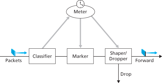
Figure 9.17 A simple Diffserv network example
marking and are forwarded along their route to the destination. On the other hand, if the traffic profile is violated, out-of-profile packets might be marked differently, might be shaped (for example, delayed so that a maximum rate constraint would be observed), or might be dropped at the network edge. The role of the metering function, shown in Figure 9.17, is to compare the incoming packet flow with the negotiated traffic profile and to determine whether a packet is within the negotiated traffic profile. The actual decision about whether to immediately remark, forward, delay, or drop a packet is a policy issue determined by the network administrator and is not specified in the Diffserv architecture.
So far, we have focused on the marking and policing functions in the Diffserv architecture. The second key component of the Diffserv architecture involves the per-hop behavior (PHB) performed by Diffserv-capable routers. PHB is rather cryptically, but carefully, defined as “a description of the externally observable forwarding behavior of a Diffserv node applied to a particular Diffserv behavior aggregate” [RFC 2475]. Digging a little deeper into this definition, we can see several important considerations embedded within:
A PHB can result in different classes of traffic receiving different performance (that is, different externally observable forwarding behaviors).
While a PHB defines differences in performance (behavior) among classes, it does not mandate any particular mechanism for achieving these behaviors. As long as the externally observable performance criteria are met, any implementation mechanism and any buffer/bandwidth allocation policy can be used. For example, a PHB would not require that a particular packet-queuing discipline (for example, a priority queue versus a WFQ queue versus a FCFS queue) be used to achieve a particular behavior. The PHB is the end, to which resource allocation and implementation mechanisms are the means.
Differences in performance must be observable and hence measurable.
Two PHBs have been defined: an expedited forwarding (EF) PHB [RFC 3246] and an assured forwarding (AF) PHB [RFC 2597]. The expedited forwarding PHB specifies that the departure rate of a class of traffic from a router must equal or exceed a configured rate. The assured forwarding PHB divides traffic into four classes, where each AF class is guaranteed to be provided with some minimum amount of bandwidth and buffering.
Let’s close our discussion of Diffserv with a few observations regarding its service model. First, we have implicitly assumed that Diffserv is deployed within a single administrative domain, but typically an end-to-end service must be fashioned from multiple ISPs sitting between communicating end systems. In order to provide end-to-end Diffserv service, all the ISPs between the end systems must not only provide this service, but most also cooperate and make settlements in order to offer end customers true end-to-end service. Without this kind of cooperation, ISPs directly selling Diffserv service to customers will find themselves repeatedly saying: “Yes, we know you paid extra, but we don’t have a service agreement with the ISP that dropped and delayed your traffic. I’m sorry that there were so many gaps in your VoIP call!” Second, if Diffserv were actually in place and the network ran at only moderate load, most of the time there would be no perceived difference between a best-effort service and a Diffserv service. Indeed, end-to-end delay is usually dominated by access rates and router hops rather than by queuing delays in the routers. Imagine the unhappy Diffserv customer who has paid more for premium service but finds that the best-effort service being provided to others almost always has the same performance as premium service!
9.5.4 Per-Connection Quality-of-Service (QoS) Guarantees: Resource Reservation and Call Admission
In the previous section, we have seen that packet marking and policing, traffic isolation, and link-level scheduling can provide one class of service with better performance than another. Under certain scheduling disciplines, such as priority scheduling, the lower classes of traffic are essentially “invisible” to the highest-priority class of traffic. With proper network dimensioning, the highest class of service can indeed achieve extremely low packet loss and delay—essentially circuit-like performance. But can the network guarantee that an ongoing flow in a high-priority traffic class will continue to receive such service throughout the flow’s duration using only the mechanisms that we have described so far? It cannot. In this section, we’ll see why yet additional network mechanisms and protocols are required when a hard service guarantee is provided to individual connections.
Let’s return to our scenario from Section 9.5.2 and consider two 1 Mbps audio applications transmitting their packets over the 1.5 Mbps link, as shown in Figure 9.18. The combined data rate of the two flows (2 Mbps) exceeds the link capacity. Even with classification and marking, isolation of flows, and sharing of unused bandwidth (of which there is none), this is clearly a losing proposition. There is simply not enough bandwidth to accommodate the needs of both applications at
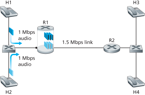
Figure 9.18 Two competing audio applications overloading the R1-to-R2 link
the same time. If the two applications equally share the bandwidth, each application would lose 25 percent of its transmitted packets. This is such an unacceptably low QoS that both audio applications are completely unusable; there’s no need even to transmit any audio packets in the first place.
Given that the two applications in Figure 9.18 cannot both be satisfied simultaneously, what should the network do? Allowing both to proceed with an unusable QoS wastes network resources on application flows that ultimately provide no utility to the end user. The answer is hopefully clear—one of the application flows should be blocked (that is, denied access to the network), while the other should be allowed to proceed on, using the full 1 Mbps needed by the application. The telephone network is an example of a network that performs such call blocking—if the required resources (an end-to-end circuit in the case of the telephone network) cannot be allocated to the call, the call is blocked (prevented from entering the network) and a busy signal is returned to the user. In our example, there is no gain in allowing a flow into the network if it will not receive a sufficient QoS to be considered usable. Indeed, there is a cost to admitting a flow that does not receive its needed QoS, as network resources are being used to support a flow that provides no utility to the end user.
By explicitly admitting or blocking flows based on their resource requirements, and the source requirements of already-admitted flows, the network can guarantee that admitted flows will be able to receive their requested QoS. Implicit in the need to provide a guaranteed QoS to a flow is the need for the flow to declare its QoS requirements. This process of having a flow declare its QoS requirement, and then having the network either accept the flow (at the required QoS) or block the flow is referred to as the call admission process. This then is our fourth insight (in addition to the three earlier insights from Section 9.5.2,) into the mechanisms needed to provide QoS.
Insight 4: If sufficient resources will not always be available, and QoS is to be guaranteed, a call admission process is needed in which flows declare their QoS requirements and are then either admitted to the network (at the required QoS) or blocked from the network (if the required QoS cannot be provided by the network).
Our motivating example in Figure 9.18 highlights the need for several new network mechanisms and protocols if a call (an end-to-end flow) is to be guaranteed a given quality of service once it begins:
Resource reservation. The only way to guarantee that a call will have the resources (link bandwidth, buffers) needed to meet its desired QoS is to explicitly allocate those resources to the call—a process known in networking parlance as resource reservation. Once resources are reserved, the call has on-demand access to these resources throughout its duration, regardless of the demands of all other calls. If a call reserves and receives a guarantee of x Mbps of link bandwidth, and never transmits at a rate greater than x, the call will see loss- and delay-free performance.
Call admission. If resources are to be reserved, then the network must have a mechanism for calls to request and reserve resources. Since resources are not infinite, a call making a call admission request will be denied admission, that is, be blocked, if the requested resources are not available. Such a call admission is performed by the telephone network—we request resources when we dial a number. If the circuits (TDMA slots) needed to complete the call are available, the circuits are allocated and the call is completed. If the circuits are not available, then the call is blocked, and we receive a busy signal. A blocked call can try again to gain admission to the network, but it is not allowed to send traffic into the network until it has successfully completed the call admission process. Of course, a router that allocates link bandwidth should not allocate more than is available at that link. Typically, a call may reserve only a fraction of the link’s bandwidth, and so a router may allocate link bandwidth to more than one call. However, the sum of the allocated bandwidth to all calls should be less than the link capacity if hard quality of service guarantees are to be provided.
Call setup signaling. The call admission process described above requires that a call be able to reserve sufficient resources at each and every network router on its source-to-destination path to ensure that its end-to-end QoS requirement is met. Each router must determine the local resources required by the session, consider the amounts of its resources that are already committed to other ongoing sessions, and determine whether it has sufficient resources to satisfy the per-hop QoS requirement of the session at this router without violating local QoS guarantees made to an already-admitted session. A signaling protocol is needed to coordinate these various activities—the per-hop allocation of local resources, as well as the overall end-to-end decision of whether or not the call has been able to reserve suf
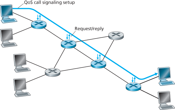
Figure 9.19 The call setup process
ficient resources at each and every router on the end-to-end path. This is the job of the call setup protocol, as shown in Figure 9.19. The RSVP protocol [Zhang 1993, RFC 2210] was proposed for this purpose within an Internet architecture for providing quality-of-service guarantees. In ATM networks, the Q2931b protocol [Black 1995] carries this information among the ATM network’s switches and end point.
Despite a tremendous amount of research and development, and even products that provide for per-connection quality of service guarantees, there has been almost no extended deployment of such services. There are many possible reasons. First and foremost, it may well be the case that the simple application-level mechanisms that we studied in Sections 9.2 through 9.4, combined with proper network dimensioning (Section 9.5.1) provide “good enough” best-effort network service for multimedia applications. In addition, the added complexity and cost of deploying and managing a network that provides per-connection quality of service guarantees may be judged by ISPs to be simply too high given predicted customer revenues for that service.