11.10 Virtualization in Windows
In the early 2000s, as computers were getting larger and more powerful, the industry started turning to virtual machine technology to partition large machine into a number of smaller virtual machines sharing the same physical hardware. This technology was originally used primarily in data centers or hosting environments. In the next decade, however, attention turned to more fine-grained software virtualization and containers came into fashion.
Docker Inc. popularized the use of containers on Linux with its popular Docker container manager. Microsoft added support for these types of containers to Windows in Windows 10 and Windows Server 2016 and partnered with Docker Inc. so that customers could use the same popular management platform on Windows. Additionally, Windows started shipping with the Microsoft Hyper-V hypervisor so that the OS itself could leverage hardware virtualization to increase security. In this section, we will first look at Hyper-V and its implementation of hardware virtualization. Then we will study containers built purely from software and describe some of the OS features that leverage hardware virtualization features.
11.10.1 Hyper-V
Hyper-V is Microsoft’s virtualization solution for creating and managing virtual machines. The hypervisor sits at the bottom of the Hyper-V software stack and provides the core hardware virtualization functionality. It is a Type-1 (bare metal) hypervisor that runs directly on top of the hardware. The hypervisor uses virtualization extensions supported by the CPU to virtualize the hardware such that multiple guest operating systems can run concurrently, each in its own isolated virtual machine, called a partition. The hypervisor works with the other Hyper-V components in the virtualization stack to provide virtual machine management (such as startup, shutdown, pause, resume, live migration, snapshots, and device support). The virtualization stack runs in a special privileged partition called the root partition. The root partition must be running Windows, but any operating system, such as Linux, can be running in guest partitions which are also called child partitions. While it is possible to run guest operating systems that are completely unaware of virtualization, performance will suffer. Nowadays, most operating systems are enlightened to run as a guest and include guest counterparts to the root virtualization stack components which help provide higher-performance paravirtualized disk or network I/O. An overview of Hyper-V components is given in Fig. 11-50. We will discuss these components in the upcoming sections.
Figure 11-50
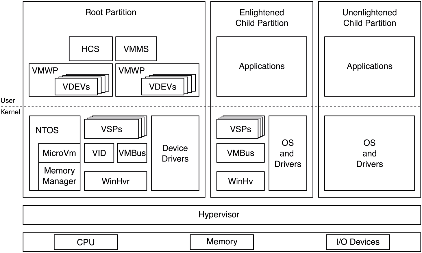
Hyper-V virtualization components in the root and child partitions.
Hypervisor
The hypervisor is a thin layer of software that runs between the hardware and the operating systems it is hosting. It is the most privileged software on the system and therefore needs to have a minimal attack surface. For this reason, it delegates as much functionality as possible to the virtualization stack running in the root partition.
The hypervisor’s most important job is to virtualize hardware resources for its partitions: processors, memory, and devices. Each partition is assigned a set of virtual processors (VPs) and guest physical memory. The hypervisor manages these resources very similar to processes and threads in the operating system. The hypervisor internally represents each partition with a process data structure and each VP with a thread. From this perspective, each partition is an address space and each VP is a schedulable entity. As such, the hypervisor also includes a scheduler to schedule VPs on physical processors.
In order to virtualize processors and memory, the hypervisor relies on virtualization extensions provided by the underlying hardware. Intel, AMD, and ARM have slight variations in what they offer, but they are all conceptually similar. In a nutshell, the hardware defines a higher privilege level for the hypervisor and allows it to intercept various operations that occur while a processor is executing in guest mode. For example, when a clock interrupt occurs, the hypervisor gets control and can decide to switch out the currently running VP and pick another one, potentially belonging to a different partition. Or, it can decide to inject the interrupt into the currently running VP for the guest OS to handle. Guest partitions can explicitly call the hypervisor—similar to how a user-mode process can make a system call into the kernel—using a hypercall, which is a trap to the hypervisor, analogous to a system call, which traps to the kernel.
For memory virtualization, the hypervisor takes advantage of SLAT (Second Level Address Translation) support provided by the CPU which essentially adds another level of page tables to translate GPAs (Guest Physical Addresses) to SPAs (Server Physical Addresses) This is known as EPT (Extended Page Tables) on Intel, NPT (Nested Page Tables) on AMD, and stage 2 translation on arm64. The hypervisor uses the SLAT to ensure that partitions cannot see each other’s or the hypervisor’s memory (unless explicitly desired). The SLAT for the root partition is set up in a 1:1 mapping such that root GPAs correspond to SPAs. The SLAT also allows the hypervisor to specify access rights (read, write, execute) on each translation which override any access rights the guest may have specified in it first-level page tables. This is important as we will see later.
When it comes to scheduling VPs on physical processors, the hypervisor supports three different schedulers:
Classic scheduler: The classic scheduler is the default scheduler used by the hypervisor. It schedules all non-idle VPs in round-robin fashion, but it allows adjustments such as setting affinity for VPs to a set of processors, reserving a percentage of processor capacity and setting limits and relative weights which are used when deciding which VP should run next.
Core scheduler: The core scheduler is relevant on CPUs that implement SMT (Symmetric Multi-Threading). SMT exposes two LPs (Logical processors), which share the resources of a single processor core. This is done to maximize utilization of processor hardware resources, but has two potentially significant downsides (so far). First, one SMT thread can impact the performance of its sibling because they share hardware resources like caches. Also, one SMT thread can use hardware side-channel vulnerabilities to infer data accessed by its sibling. For these reasons, it is not a great idea, from a performance and security isolation perspective, to run VPs belonging to different partitions on SMT siblings. That’s the problem the core scheduler solves; it schedules an entire core, with all of its SMT threads to a single partition at a time. Typically, the partition is SMTaware, so it has two VPs corresponding to the LPs in that core. Azure exclusively uses the core scheduler.
Root scheduler: When the root scheduler is enabled, the hypervisor itself does not do any VP scheduling. Instead, a virtualization stack component running in the root, known as the VID (Virtualization Infrastructure Driver) creates a system thread for each guest VP, called VP-backing threads to be scheduled by the Windows thread scheduler. Whenever one of these threads gets to run, it makes a hypercall to tell the hypervisor to run the associated VP. Whereas the other schedulers treat guest VPs as black boxes—as should be the case for most virtual machine scenarios—the root scheduler allows for various enlightenments (paravirtualizations) enabling better integration between the guest and the host. For example, one enlightenment allows the guest to inform the host about the priorities of threads currently running on its VPs. The host scheduler can reflect these priority hints onto the corresponding VP-backing threads and schedule them accordingly, relative to other host threads. The root scheduler is enabled by default on client versions of Windows.
The Virtualization Stack
While the hypervisor provides hardware virtualization for guest partitions, it takes a lot more than that to run virtual machines. The virtualization stack, composed of several component across kernel-mode and user-mode, manages virtual machine memory, handles device access, and orchestrates VM states such as start, stop, suspend, resume, live migration, and snapshot.
As shown in Fig. 11-50, WinHvr.sys is the lowest layer of the virtualization stack in the root OS. Its enlightened guest counterpart is WinHv.sys in a Windows guest or LinuxHv in a Linux guest. It’s the hypervisor interface driver which exposes APIs to facilitate communicating with the hypervisor rather than directly issuing hypercalls. It’s the logical equivalent of ntdll.dll in user-mode which hides the system call interface behind a nicer set of exports.
VID.sys, the virtualization infrastructure driver, is responsible for managing memory for virtual machines. It exposes interfaces to user-mode virtualization stack components to construct the GPA space of a guest which includes regular guest memory as well as memory-mapped I/O space (MMIO). In response to these requests, the VID allocates physical memory from the kernel memory manager and asks the hypervisor, via WinHvr.sys, to map guest GPAs to those SPAs. The hypervisor needs physical memory to construct the SLAT hierarchy for each guest. The necessary memory for such metadata is allocated by the VID and deposited into the hypervisor, as necessary.
VMBus is another keykernel-mode virtualization stack component. Its job is to facilitate communication between partitions. It does this by setting up shared memory between partitions (e.g., a guest and the root) and taking advantage of synthetic interrupt support in the hypervisor to get an interrupt injected into the relevant partition when a message is pending. VMBus is used in paravirtualized I/O.
VSPs and VSCs are virtual service providers and clients that run in the root and guest partitions, respectively. The VSPs communicate with their guest counterparts over VMBus to provide various services. The most common use of VSPs is for paravirtualized and accelerated devices, but other applications such as syncing time in the guest or implementing dynamic memory via ballooning also exist.
The user-mode virtualization components are for managing VMs as well as device support and orchestration of VM operations such as start, stop, pause, resume, live migration, snapshot, etc. VMMS (Virtual Machine Management Service) exposes interfaces for other management tools to query and manage virtual machines. HCS performs a similar task for containers. For each VM, VMMS creates a virtual machine worker process, VMWP.exe. VMWP manages the state of the VM and its state transitions. It includes VDEVs (Virtual Devices), which represent things like the virtual motherboard, disks, networking devices, BIOS, keyboard, mouse, etc. As the virtual machine boots and VDEVs are ‘‘powered on,’’ they set up I/O ports or MMIO ranges in the GPA space through the VID driver or they communicate with their VSP driver to initiate VMBus channel set up with the corresponding VSC in the guest.
Device I/O
There are several ways Hyper-V can expose devices to its guests depending on how enlightened the guest OS is and the level of virtualization support in the hardware.
Emulated devices: An unenlightened guest communicates with devices through I/O ports or memory-mapped device registers. For emulated devices, the VDEV sets up these ports and GPA ranges to cause hypervisor intercepts when accessed. The intercepts are then forwarded to the VDEV running in the VM worker process through the VID driver. In response, the VDEV initiates the I/O requested by the guest and resumes the guest VP. Typically, when the I/O is complete, the VDEV will inject a synthetic interrupt into the guest via the VID and the hypervisor to signal completion. Emulated devices require too many context switches between the guest and the host and are not appropriate for high-bandwidth devices, but are perfectly OK for devices like keyboard and mouse.
-
Paravirtualized devices: When a synthetic device is exposed to a guest partition from its VDEV, an enlightened guest will load the corresponding VSC driver which sets up VMBus communication with its VSP in the root. A very common example of this is storage. Virtual hard disks are typically used with VMs and are exposed via the StorVSP and StorVSC drivers. Once the VMBus channel is set up, I/O requests received by the StorVSC are communicated to the StorVSP which then issues them to the corresponding virtual hard disk via the vhdmp.sys driver. Figure 11-51 illustrates this flow.
Figure 11-51
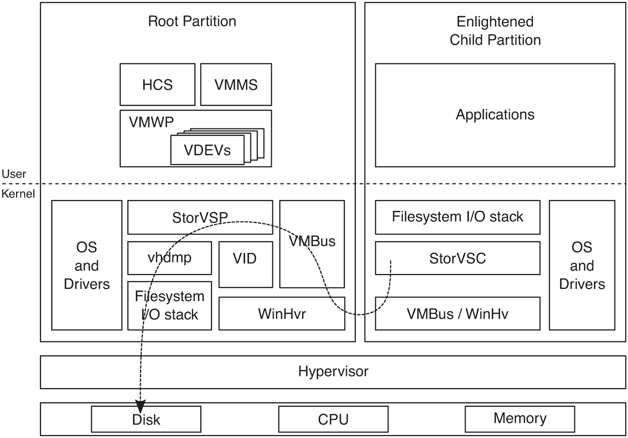
Flow of parvirtualized I/O for an enlightened guest OS.
Hardware-accelerated devices: While paravirtualized I/O is much more efficient than device emulation, it still has too much root CPU overhead especially when it comes to today’s high-end networking devices used in data centers or NVMe disks. Such devices support SR-IOV (Single-Root I/O Virtualization) or DDA (Discrete Device Assignment). Either way, the virtual PCI VDEV, working with the vPCI VSP/VSC, exposes the device to the guest on the virtual PCI bus. This is either a virtual function (VF) for SR-IOV devices or a physical function (PF) for DDA. The guest loads the corresponding device driver and is able to communicate directly with the device because its MMIO space is mapped into guest memory via the IOMMU. The IOMMU is also configured by the hypervisor to ensure that the device can only perform I/O to pages exposed to the guest.
VA-backed VMs
Typically, the VID driver allocates dedicated physical memory for each virtual machine and maps it into the GPA space through the SLAT. This memory belongs to the VM whether it is using it or not. Hyper-V also supports a different model for managing VM memory, called VA-backed VMs, which provides more flexibility.
Instead of allocating physical pages up-front, VA-backed VM GPA space is backed by virtual memory allocated from a minimal process (see Sec. 11.4.3) called vmmem. The VID creates a vmmem process for each VA-backed VM and allocates virtual memory in that process corresponding to the RAM size configured for the VM, using an internal variant of VirtualAlloc. The mapping between the vmmem virtual address range and the guest GPA space is managed by an NT kernel component called MicroVm, which is tightly integrated with the memory manager.
A VA-backed VM starts booting with a largely empty SLAT. As its VPs access guest physical pages, they hit SLAT page faults, leading to memory intercepts into the hypervisor which are forwarded to the VID and then to MicroVm. MicroVm determines the virtual address that correspond to the faulting GPA and asks the memory manager to perform regular demand-zero fault handling, which involves allocating a new physical page and updating the PTE corresponding to the vmmem virtual address. After the fault is resolved and the virtual address is added to the vmmem working set, MicroVm calls the hypervisor to update the SLAT mapping from the faulting GPA to the newly allocated page. After that, the VID can return back to the hypervisor, resolving the guest fault and resuming the guest VP.
The reverse can also happen. If the host memory manager decides to trim a valid page from the vmmem working set, MicroVm will ask the hypervisor to invalidate the SLAT mapping for the corresponding GPA. The next time guest accesses that GPA, it will take a SLAT fault which will need to be resolved as described earlier.
The design of VA-backed VMs allows the host memory management to treat the virtual machine (represented by the vmmem process) just like any other process and apply its memory management bag of tricks to it. Mechanisms like aging, trimming, paging, prefetching, page combining, and compression can be used to manage VM memory more efficiently.
VA-backed VMs enable another significant memory optimization: file sharing. While there are many applications of file sharing, a particularly important one is when multiple guests are running the same OS or when a guest is running the same OS as the host. Similar to how guest RAM is associated with a virtual address range in vmmem, a binary can be mapped to the vmmem address space using the equivalent of MapViewOfFile. The resulting address range is exposed to the guest as a new GPA range and the mapping is tracked by MicroVm. That way, accesses to the GPA range will result in memory intercepts which will be resolved by file pages backed by the binary. The critical point is that host processes that map the same file will use the exact same file page in physical memory.
So far, we described how a file mapping can be exposed to the guest as a GPA range while being shared by host processes (or by GPA ranges in other VMs). How does the guest use the GPA range as a file? In the guest, an enlightened file system driver (called wcifs.sys on Windows) takes advantage of a memory manager feature called Direct Map to expose CPU-addressable memory as file pages that the memory manager can directly use. Rather than allocating new physical pages, copying file data into those pages and then pointing PTEs to them, the memory manager updates PTEs to point directly to the CPU-addressable file pages themselves. This mechanism allows all processes in the guest OS to share the same GPAs that were exposed from the vmmem file mapping. Figure 11-52 shows how VA-backed VM memory is organized.
Figure 11-52
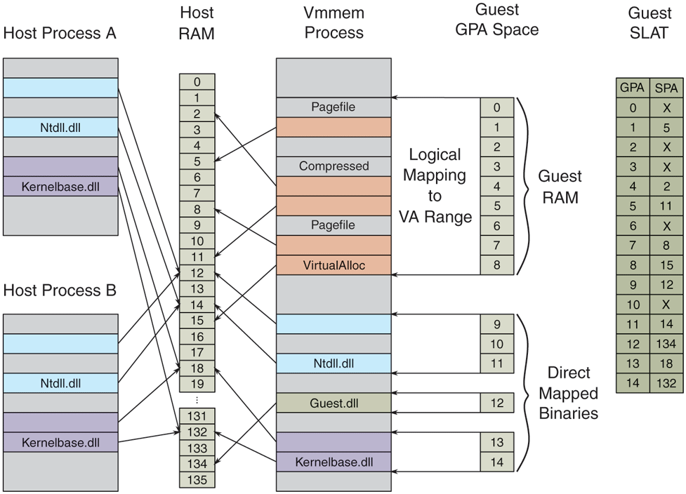
VA-backed VM’s GPA space is logically mapped to virtual address ranges in its vmmem process on the host.
In addition to the optimizations described so far, the VA-backed VM design also allows various memory management enlightenments in the guest to further optimize memory usage. One important example is hot/cold memory enlightenments. Via hypercalls, the guest memory manager can provide hints to the host about GPAs that are more or less likely to get accessed soon. In response, the host can make sure that those pages are resident and valid in the SLAT (for ‘‘hot’’ pages) or trim them out of the vmmem working set (for ‘‘cold’’ pages). Windows guests take advantage of this enlightenment to cold-hint pages in the back of the zeroed page list. That results in the underlying host physical pages getting freed into the zero page list on the host because of the zero-page detection done by the memory manager during working set trim (see Sec. 11.5.3). Hot hints are used for pages at the head of the free, zero, and standby lists if these have previously been cold-hinted.
11.10.2 Containers
Hardware-based virtualization is very powerful but sometimes provides more isolation than desired. In many cases, it is preferable to have more fine-grained virtualization. Windows 10 added support for containers which leverages fine-grained software virtualization. This section will investigate a few uses for more finegrained virtualization and then examine how it is implemented.
Earlier in Sec. 11.2.1 the modern app architecture was discussed, one of the benefits being reliable install/uninstall and the ability to deliver apps via the Microsoft Store. In Windows 8, only modern apps were delivered via the store—leaving out the enormous library of existing Windows applications. Microsoft wanted to provide a way for software vendors to package their existing applications to be delivered from the store while maintaining the benefits the store was meant to provide. The solution was to encourage applications to be distributed via MSIX packages and allow the installation of the application to be virtualized. Rather than requiring an installer to modify the file system and registry to install the app, those modifications would be virtualized. When the application is launched, the system creates a container with an alternate view of the file system and registry namespace that make it look like the application has been installed (to the application about to be run). If the user decides to uninstall the application, the MSIX package is deleted, but there is no longer a need to go and remove application files and state from the file system and registry.
Windows 10 also introduced a feature similar to Linux containers, known as Windows Server Containers. A Windows Server Container provides an environment that looks like a full virtual machine. The container gets its own IP address, can have its own computer name on the network, its own set of user accounts, etc. However, a Windows Server Container is much lighter weight than a VM because it shares the kernel with the host, only the user mode processes are replicated. These types of containers do not provide the same level of isolation as a VM but provide a very convenient deployment model and reduce the concern of running two applications that normally could not coexist.
Namespace Virtualization
The underlying technology that containers build on is known as namespace virtualization. Rather than virtualizing hardware, as VMs do, containers make it possible for one or more processes to run with a slightly different view of various namespaces.
To provide namespace virtualization support, Windows 10 introduced the notions of Silos. Silos are an extension to the job object (see Sec. 11.4.1) that allow for namespace virtualization. Silos make it possible to provide alternative views of namespaces to the processes running within them. Silos are the fundamental building block for implementing container support in Windows. There are in fact two types of Silos. The first is known as an Application Silo. App Silos provide namespace virtualization only. A job is converted into a silo via a SetInformationJobObject API call to enable the namespace virtualization features on the job. Rather than require a separate call to promote a job object into a silo, Microsoft could have just changed the implementation of job objects such that all jobs had namespace virtualization support. However, that would have caused all job objects to require more memory so instead a pay for play model was adopted. The second type of silo is known as a Server Silo. Server silos are used to implement Windows server containers (see below). Because server containers provide the illusion of a full machine, some kernel mode state needs to be instanced per container. Server silos build on app silos in that in addition to namespace virtualization it also allows various kernel components to maintain separate copies of their state per container. Server silos require much more storage than an app silo so the payfor-play model is again adopted so that this extra storage is only required for jobs promoted into full server silos.
When a job is created and promoted into an app silo, it is considered a namespace container. Prior to launching processes within the container, the various namespaces being virtualized must be configured. The most prominent namespaces are the file system and registry namespaces. Virtualizing these namespaces is done via filter drivers. During silo initialization, a user mode component will send IOCTLs to the various namespace filters to configure them for how to virtualize the given namespace. However, no container state is associated with the filters themselves. Instead, the model is to associate all state required to do namespace virtualization with the silo itself. During startup, namespace filter drivers request a silo slot index from the system and store it in a global variable. The silo then provides a key/value store to the drivers. They can store any object manager object (see Sec. 11.3.3) in the slot associated with their index. If a driver wants to store state that is not in the form of an object manager object, it can use the new kernel API PsCreateSiloContext to create an object with storage of the required size and pool type. The namespace filter packages up the state required for virtualizing the namespace and stores it in the silo slot for future reference.
Once all namespace providers are configured, the first application in the container is launched. As that application starts to run, it will inevitably start to access various namespaces. When an IO request reaches a given namespace, the namespace filter will check to see if virtualization is required. It will call the PsGetSiloContext API passing its slot index to retrieve any configuration required to virtualize the namespace. If the given namespace is not being virtualized for the running thread, then the call will return a status code indicating there is nothing in the slot, and the namespace filter will simply pass the IO request to the next driver in the stack (see Sec. 11.7.3 for details on driver stacks). However, if configuration information was found in the slot, the namespace filter will use it to determine how to virtualize the namespace. For example, the filter may need to modify the name of the file being opened before passing the request down the stack.
The benefit of associating all configuration with the silo and having the storage slots hold object manager objects is that cleanup is simple. When the last process in the silo goes away, and the last reference to the silo goes away the system can just run down the entries in each storage slot and drop the reference to the associated object. This is very similar to what the system does when a process exits, and its handle table is run down.
Server containers are a bit more complicated than application silos as many more namespaces must be virtualized to create the illusion of an isolated machine. For example, application silos typically share most namespaces with the host and often only need a few new resources inserted into the observed namespace. With server containers all namespaces must be virtualized. This includes the full object manager namespace, the file system and registry, the network namespace, the process and thread ID namespace, etc. If, for example, the network namespace was not virtualized a process in one container might use a port that a process in another container needed. By giving each container its own IP address and port space, such conflicts are avoided. Additionally, the process and thread ID namespaces are virtualized to avoid one container seeing or having access to processes and threads from another container.
In addition to the larger set of namespaces to be virtualized, server containers also require private copies of various kernel state. A Windows administrator can normally configure certain global system state that effects the entire machine. To provide an administrative process running within the container this same type of control, the kernel was updated to allow this state to apply per container rather than globally. The result is that much of the kernel state that was previously stored in global variables is now referenced per container. There is a notion of a host container which is where the host’s state is stored.
Booting a server silo begins in the same way as creating an application silo. The job object is promoted into a silo and the namespace configuration is done. Unlike standard app containers, server containers get a full private object manager namespace. The root of the server containers namespace is an object manager directory on the host. This allows the host full visibility and access to the container which aids in management tasks. For example, the following directory may represent the root of a server container namespace: \Silos\100. In this example, 100 is the job identifier of the silo backing the server container. This directory is also prepopulated with a variety of objects such that the object manager namespace for the container will look like what the host’s namespace looks like just before launching the first user mode process. Some of those objects are shared with the host and are exposed to the container with a special type of symbolic link that allow host objects to be accessed from within the container.
Once the container’s namespace is setup, the next step is to promote the silo to a server silo. This is done with another SetInformationJobObject call. Promoting the silo to a server silo allocates additional data structures used to maintain instanced copies of kernel state. Then the kernel invokes enlightened kernel components and give them an opportunity to initialize their state and do any other prep work required. If any of these steps fail, then the server silo boot fails, and the container is torn down.
Finally, the initial user mode process smss.exe is started within the container. At this p,oint the user mode portions of the OS boot up. A new instance of csrss.exe is started (the Win32 subsystem process), a new instance of lsass.exe (the local security authority subsystem), a new service control manager, etc. For the most part, everything works in the same way it would if booting user mode on the host. Some things are different in the container, though. For example, an interactive user session is not created—it is not needed since the container is headless. But these changes are just configuration changes, driven by existing mechanisms. The difference in behavior is because the virtualized registry state for the container is configured that way.
As the container boots, it is booting from a VHD (Virtual Hard Disk). However, that VHD is mostly empty. The file system virtualization driver, wcifs.sys, provides the appearance to the processes running within the container that the hard disk is fully populated. The backing store for the container’s disk contents is spread across one or more directories on the host as illustrated in Fig. 11-53. Each of these host directories represents an image layer. The bottom-most layer is known as the base layer and is provided by Microsoft. Subsequent layers are various deltas to this bottom layer, potentially changing configuration settings in the virtualized registry hives, or additions, changes, or deletions (represented with special tombstone files to the file system. At runtime, the file system namespace filter merges each of these directories together to create the view exposed to the container. Each of these layers is immutable and can be shared across containers. As the container runs and makes changes to the file system, those changes are captured on the VHD exposed to the container. In this way, the VHD will contain deltas from the layers below. It is possible to later shut down the container and make a new layer based on the contents of the VHD. Or if the container is no longer needed, it can be disposed of, and all persisted side effects deleted.
Figure 11-53
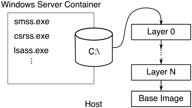
The contents of the VHD exposed to the container is backed by a set of host directories that are merged at runtime to make up the container file system contents.
Certain operations are blocked within a container. For example, a container is not allowed to load a kernel driver as doing so might allow an avenue to escape the containment. Additionally, certain functionality such as changing the time is blocked within the container. Typically, such operations are protected by privilege checks. These privilege checks are augmented when running in the container so that the operations that should be blocked within a container are blocked regardless of the privilege enabled in the caller’s token. Other operations, such as changing the time zone, are allowed if the required privilege is held but the operation is virtualized so that only processes within the container use the new time zone.
A container can be terminated in a few ways. First, it can be terminated from the outside (via the management stack) which is like a forced shutdown. Second, it can be terminated from inside the container when a process calls a Win32 API to shut down Windows, such as ExitWindowsEx or InitiateSystemShutdown. When the request to shut down the machine reaches the kernel and if the request originated in a container, the kernel terminates the container rather the shutting down the host. A container can also be shut down if a critical process within the container crashes. This would normally result in a host blue screen, but if the critical process was in a container, the container will be terminated rather than causing a blue screen.
Hyper-V Isolated Containers
Server Silos provide a high degree of isolation based on namespace isolation. Microsoft advertises these containers as being suitable for enterprise multitenancy or non-hostile workloads. However, there are times when it is desirable to run hostile workloads within a container. For those scenarios, Hyper-V isolated containers are the solution. These containers leverage hardware-based virtualization mechanism to provide a very secure boundary between the container and its host.
One of the primary design goals of Windows Containers was to not require an administrator to decide upfront what type of container to use. The same artifacts should be usable with either a Windows Server Container or a Hyper-V Isolated Container. The approach taken was to always run a server silo for the container, but in some cases, it is run on the host (Windows Server Containers) and in others, it is run within something known as a Utility VM (Hyper-V Isolated Containers). The Utility VM is created as a VA-backed VM to optimize memory usage and to allow in memory sharing of container base image binaries across running containers which significantly improves density.
The utility VM also runs a very scaled down OS instance, designed to host nothing other than server silos so that it boots quickly and uses minimal memory. When the Hyper-V isolated container is instantiated, the Utility VM is started first. Then the HCS (Host Compute Service) communicates to the GCS (Guest Compute Service) running in the Utility VM and requests the server silo to be started.
Since Hyper-V isolated containers run their own copy of the Windows kernel in the Utility VM, even a hostile workload that manages to take advantage of a flaw in the Windows kernel will not be able to attack the host. Administrators can alternate between running a server container in either a process isolated or HyperV isolated scenario with one command line switch.
Hardware Isolated Processes
Windows 10 has also introduced support for running certain processes that represent a high attack surface within Hardware Isolated Containers in some Windows editions. MDAG (Microsoft Defender Application Guard) supports running the Edge browser within a hardware isolated container. The Edge team has worked very hard to protect users when navigating to a malicious website. However, Edge is also very large and complicated and so is the underlying OS. There will always be latent bugs that bad actors can try to exploit. By running the Edge browser in a Utility VM-type environment, malicious activity can be limited to the container. And since the container’s side effects can be discarded after each run, it is possible to provide a pristine environment for each launch.
Unlike server containers which are headless, users need to see the Edge browser. This is achieved by leveraging a technology known as RAIL (Remote Apps Integrated Locally). The RDP (Remote Desktop Protocol) is used to remote the window for a single application, in this case the Edge browser, to the host. The effect is the user has the same experience as running Edge locally but with the backend processing done in a container. Copy and paste functionality is limited over RDP to avoid malicious attacks via the clipboard. Display performance is quite good due to shared memory between the host and the guest for display purposes, and a virtual GPU can even be exposed to the guest so that the guest can leverage the host GPU for rendering purposes.
In later versions of Windows 10, MDAG was extended to support running Microsoft Office applications as well. For other applications not supported directly by MDAG, there is a feature known as Windows Sandbox. Windows Sandbox uses the same underlying technology as MDAG and Hyper-V isolated containers but provides the user with a full desktop environment. The user can launch Windows Sandbox to run programs they are hesitant to run on the host.
MDAG and Windows Sandbox leverage the same OS instance installed on the host and when the host OS is serviced so is the MDAG/Sandbox environment. They also benefit from the same VA-backed VM optimizations listed above like direct mapped memory and integrated scheduler reducing the cost of running these relative to a classic VM.
VA-backed VMs are also used for running certain guest operating systems other than Windows. WSL (Windows Subsystem for Linux) and WSA (Windows Subsystem for Android) are also built on VA-backed VMs to run Linux and Android operating systems on top of Windows in a more efficient way than regular VMs. While these operating systems do not (yet) implement all of the memory management and root scheduler enlightenments Windows guests do, they are able to take full advantage of host-side memory management optimizations like memory compression and paging.
11.10.3 Virtualization-Based Security
We covered how virtualization can be used to run virtual machines, containers, and security-isolated processes. Windows also leverages virtualization to improve its own security. The fundamental problem is that there is too much code running in kernel-mode, both as part of Windows and third-party drivers. The breadth of Windows in the world and the diversity of hardware it supports has resulted in a very healthy ecosystem of kernel-mode drivers, despite moving a lot of them into user-mode. All kernel-mode code executes at the same CPU privilege level and, therefore, any security vulnerability can enable an attacker to disrupt code flow, modify or steal security-sensitive data in the kernel. A higher privilege level is necessary to ‘‘police’’ kernel mode and to protect security-sensitive data.
Virtual Secure Mode provides a secure execution environment by leveraging virtualization to establish new trust boundaries for the operating system. These new trust boundaries can limit and control the set of memory, CPU and hardware resources kernel-mode software can access such that even if kernel-mode is compromised by an attacker, the entire system is not compromised.
VSM provides these trust boundaries through the concept of VTLs (Virtual Trust Levels). At its core, a VTL is a set of memory access protections. Each VTL can have a different set of protections, controlled by code running at a higher, more privileged VTL. Therefore, higher VTLs can police lower VTLs by configuring what access they have to memory. Semantically, this is similar to the relationship between user-mode and kernel-mode enforced by CPU hardware. For example, a higher VTL can use this capability in the following ways:
It can prevent a lower VTL from accessing certain pages which may contain security-sensitive data or data owned by the higher VTL.
It can prevent a lower VTL from writing to certain pages to prevent overwrite of critical settings, data structures, or code.
It can prevent a lower VTL from executing code pages unless they are ‘‘approved’’ by the higher VTL.
For each partition, including the root and guest partitions, the hypervisor supports multiple VTLs. Being in the same partition, all VTLs share the same set of virtual processors, memory, and devices, but each VTL can have different access rights to those resources. Memory protections for VTLs are implemented using a per-VTL SLAT. The IOMMU is leveraged to enforce memory access protection for devices. As such, it is not possible for even kernel-mode code to circumvent these protections. Similar to how CPUs implement different privilege levels, each VTL has its own virtual processor state, isolated from lower VTLs. A virtual processor can transition between VTLs (similar to making a system call from user-mode into kernel-mode and back). When entering a particular VTL, the VP context is updated with the target VTL processor state and the VP is subject to that VTL’s memory access protections. Higher VTLs can also prevent lower VTLs from accessing or modifying privileged CPU registers or I/O ports, which could otherwise be used to disable the hypervisor or tamper with secure devices (like fingerprint readers). Finally, each VTL has its own interrupt subsystem, such that it can enable, disable, and dispatch interrupts without interference from lower VTLs. Even though many VTLs can be supported by the hypervisor, we will focus on VTL0 and VTL1 in this chapter.
VTL0 is the VSM normal mode in which Windows, with its user-mode and kernel-mode components, runs. VTL1 is referred to as the secure mode in which a security-focused micro-OS called the Secure Kernel runs. Figure 11-54 shows this organization. The Secure Kernel provides various security services to Windows as well as IUM (Isolated User Mode) the ability to run VTL1 user-mode programs which are completely shielded from VTL0. Windows includes IUM processes, called trustlets, which securely manage user credentials, encryption keys, as well as biometric information for fingerprint or face authentication. The overall collection of these security mechanisms is termed VBS.
Figure 11-54
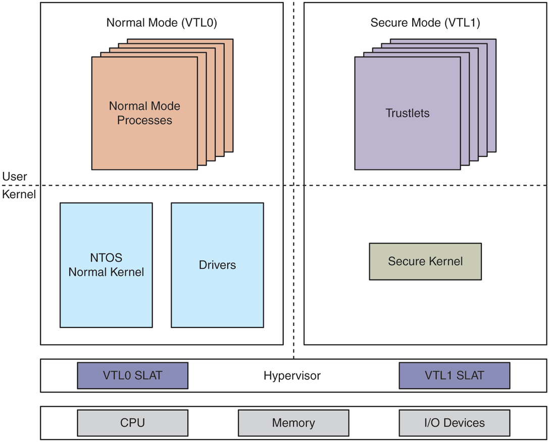
Virtual Secure Mode architecture with NT kernel in VTL0 and Secure Kernel in VTL1. VTLs share memory, CPUs, and devices, but each VTL has its own access protections for these resources, controlled by higher VTLs.
In the next section, we are going to cover the basics of Windows security and then go deeper into various security services provided by VBS.