11.3 System Structure
In the previous sections, we examined Windows as seen by the programmer writing code for user mode. Now we are going to look under the hood to see how the system is organized internally, what the various components do, and how they interact with each other and with user programs. This is the part of the system seen by the programmer implementing low-level user-mode code, like subsystems and native services, as well as the view of the system provided to device-driver writers.
Although there are many books on how to use Windows, there are fewer on how it works inside. One of the best places to look for additional information on this topic is Microsoft Windows Internals, 7th ed. Part 1 (Yosifovich et al, 2017) and Microsoft Windows Internals, 7th ed. Part 2. (Allievi et al., 2021).
11.3.1 Operating System Structure
As described earlier, the Windows operating system consists of many layers, as depicted in Fig. 11-4. In the following sections, we will dig into the lowest levels of the operating system: those that run in kernel mode. The central layer is the NTOS kernel itself, which is loaded from ntoskrnl.exe when Windows boots. NTOS itself consists of two layers, the executive, which containa most of the services, and a smaller layer which is (also) called the kernel and implements the underlying thread scheduling and synchronization abstractions (a kernel within the kernel?), as well as implementing trap handlers, interrupts, and other aspects of how the CPU is managed.
The division of NTOS into kernel and executive is a reflection of NT’s VAX/VMS roots. The VMS operating system, which was also designed by Cutler, had four hardware-enforced layers: user, supervisor, executive, and kernel corresponding to the four protection modes provided by the VAX processor architecture. The Intel CPUs also support four rings of protection, but some of the early target processors for NT did not, so the kernel and executive layers represent a software-enforced abstraction, and the functions that VMS provides in supervisor mode, such as printer spooling, are provided by NT as user-mode services.
The kernel-mode layers of NT are shown in Fig. 11-11. The kernel layer of NTOS is shown above the executive layer because it implements the trap and interrupt mechanisms used to transition from user mode to kernel mode.
Figure 11-11
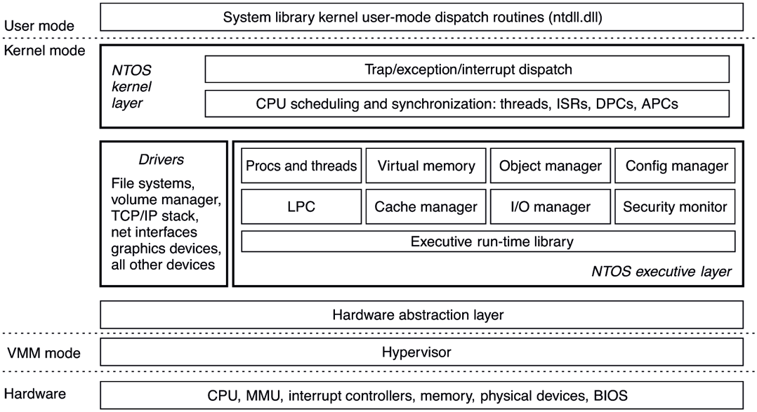
Windows kernel-mode organization.
The uppermost layer in Fig. 11-11 is the system library (ntdll.dll), which actually runs in user mode. The system library includes a number of support functions for the compiler runtime and low-level libraries, similar to what is in libc in UNIX. ntdll.dll also contains special code entry points used by the kernel to initialize threads and dispatch exceptions and user-mode asynchronous procedure calls (described later). Because the system library is so integral to the operation of the kernel, every user-mode process created by NTOS has ntdll mapped at the same address (the particular address is randomized in every boot session as a security measure). When NTOS is initializing the system, it creates a section object to use when mapping ntdll, and it also records addresses of the ntdll entry points used by the kernel.
Below the NTOS kernel and executive layers is a layer of software called the HAL (Hardware Abstraction Layer) which abstracts low-level hardware details like access to device registers and DMA operations, and the way the motherboard firmware represents configuration information and deals with differences in the CPU support chips, such as various interrupt controllers.
The lowest software layer is the hypervisor which is the core of Windows’ virtualization stack, called Hyper-V. It is a Type-1 (bare metal) hypervisor that runs on top of the hardware and supports concurrently running multiple operating systems. The hypervisor relies on the virtualization stack components running in the root operating system to virtualize guest operating systems. The hypervisor was an optional feature in earlier versions of Windows, but Windows 11 enables virtualization by default in order to provide critical security features which we will describe in subsequent sections. Hyper-V requires a 64-bit processor with hardware virtualization support and this is reflected in the minimum hardware requirements of the OS. Consequently, older computers cannot run Windows 11.
The other major components of kernel mode are the device drivers. Windows uses device drivers for any kernel-mode facilities which are not part of NTOS or the HAL. This includes file systems, network protocol stacks, and kernel extensions like antivirus and DRM (Digital Rights Management) software, as well as drivers for managing physical devices, interfacing to hardware buses, and so on.
The I/O and virtual memory components cooperate to load (and unload) device drivers into kernel memory and link them to the NTOS and HAL layers. The I/O manager provides interfaces which allow devices to be discovered, organized, and operated—including arranging to load the appropriate device driver. Much of the configuration information for managing devices and drivers is maintained in the SYSTEM hive of the registry. The plug-and-play subcomponent of the I/O manager maintains information about the hardware detected within the HARDWARE hive, which is a volatile hive maintained in memory rather than on disk, as it is completely recreated every time the system boots.
We will now examine the various components of the operating system in a bit more detail.
The Hypervisor
The Hyper-V hypervisor runs as the lowest software layer underneath Windows. Its job is to virtualize the hardware such that multiple guest operating systems can run concurrently, each in their own virtual machine, which Windows calls a partition. The hypervisor achieves this by taking advantage of virtualization exCtensions supported by the CPU (VT-X on Intel, AMD-V on AMD and ARMv8-A on ARM processors) to confine each guest to its assigned memory, CPU, and hardware resources, isolated from other guests. Also, the hypervisor intercepts many of the privileged operations performed by guest operating systems and emulates them to maintain the illusion. An operating system running on top of the hypervisor executes threads and handles interrupts on abstractions of the physical processors called virtual processors. The hypervisor schedules the virtual processors on physical processors.
Being a Type-1 hypervisor, the Windows hypervisor runs directly on the underlying hardware, but uses its virtualization stack components in the root operating system to provide device support services to its guests. For example, an emulated disk read request initiated by a guest operating system is handled by the virtual disk controller component running in user-mode by performing the requested read operation using regular Win32 APIs. While the root operating system must be Windows when running Hyper-V, other operating systems, such as Linux, can be run in the guest partitions. A guest operating system may perform very poorly unless it has been modified (i.e., paravirtualized) to work with the hypervisor.
For example, if a guest operating system kernel is using a spinlock to synchronize between two virtual processors and the hypervisor reschedules the virtual processor holding the spinlock, the lock hold time may increase by several orders of magnitude, leaving other virtual processors running in the partition spinning for very long periods of time. To solve this problem, a guest operating system is enlightened to spin only a short time before calling into the hypervisor to yield its physical processor to run another virtual processor.
While the main job of the hypervisor is to run guest operating systems, it also helps improve the security of Windows by exposing a secure execution environment called VSM (Virtual Secure Mode) in which a security-focused micro-OS called the SK (Secure Kernel) runs. The Secure Kernel provides a set of security services to Windows, collectively termed VBS (Virtualization-Based Security). These services help protect code flow and integrity of OS components and maintain consistency of sensitive OS data structures as well as processor registers. In Sec. 11.10 we will discuss the inner workings of Hyper-V virtualization stack and learn how Virtualization-based Security works.
The Hardware Abstraction Layer
One goal of Windows is to make the system portable across hardware platforms. Ideally, to bring up an operating system on a new type of computer system, it should be possible to just recompile the operating system on the new platform. Unfortunately, it is not this simple. While many of the components in some layers of the operating system can be largely portable (because they mostly deal with internal data structures and abstractions that support the programming model), other layers must deal with device registers, interrupts, DMA, and other hardware features that differ significantly from machine to machine.
Most of the source code for the NTOS kernel is written in C rather than assembly language (only 2% is assembly on x86, and less than 1% on x64). However, all this C code cannot just be scooped up from an x86 system, plopped down on, say, an ARM system, recompiled, and rebooted owing to the many hardware differences between processor architectures that have nothing to do with the different instruction sets and which cannot be hidden by the compiler. Languages like C make it difficult to abstract away some hardware data structures and parameters, such as the format of page table entries and the physical memory page sizes and word length, without severe performance penalties. All of these, as well as a slew of hardware-specific optimizations, would have to be manually ported even though they are not written in assembly code.
Hardware details about how memory is organized on large servers, or what hardware synchronization primitives are available, can also have a big impact on higher levels of the system. For example, NT’s virtual memory manager and the kernel layer are aware of hardware details related to cache and memory locality. Throughout the system, NT uses compare&swap synchronization primitives, and it would be difficult to port to a system that does not have them. Finally, there are many dependencies in the system on the ordering of bytes within words. On all the systems NT has ever been ported to, the hardware was set to little-endian mode.
Besides these larger issues of portability, there are also minor ones even between different motherboards from different manufacturers. Differences in CPU versions affect how synchronization primitives like spin-locks are implemented. There are several families of support chips that create differences in how hardware interrupts are prioritized, how I/O device registers are accessed, management of DMA transfers, control of the timers and real-time clock, multiprocessor synchronization, working with firmware facilities such as ACPI (Advanced Configuration and Power Interface), and so on. Microsoft made a serious attempt to hide these types of machine dependencies in a thin layer at the bottom called the HAL, as mentioned earlier. The job of the HAL is to present the rest of the operating system with abstract hardware that hides the specific details of processor version, support chipset, and other configuration variations. These HAL abstractions are presented in the form of machine-independent services (procedure calls and macros) that NTOS and the drivers can use.
By using the HAL services and not addressing the hardware directly, drivers and the kernel require fewer changes when being ported to new processors—and in most cases can run unmodified on systems with the same processor architecture, despite differences in versions and support chips.
The HAL does not provide abstractions or services for specific I/O devices such as keyboards, mice, and disks or for the memory management unit. These facilities are spread throughout the kernel-mode components, and without the HAL the amount of code that would have to be modified when porting would be substantial, even when the actual hardware differences were small. Porting the HAL itself is straightforward because all the machine-dependent code is concentrated in one place and the goals of the port are well defined: implement all of the HAL services. For many releases, Microsoft supported a HAL Development Kit allowing system manufacturers to build their own HAL, which would allow other kernel components to work on new systems without modification, provided that the hardware changes were not too great. This practice is no longer active and as such, there’s little reason to maintain the HAL layer in a separate binary, hal.dll. With Windows 11, the HAL layer has been merged into ntoskrnl.exe. Hal.dll is now a forwarder binary kept around to maintain compatibility with drivers that use its interfaces all of which are redirected to the HAL layer in ntoskrnl.exe.
As an example of what the hardware abstraction layer does, consider the issue of memory-mapped I/O vs. I/O ports. Some machines have one and some have the other. How should a driver be programmed: to use memory-mapped I/O or not? Rather than forcing a choice, which would make the driver not portable to a machine that did it the other way, the hardware abstraction layer offers procedures for driver writers to use for reading the device registers others for writing them:
uc = READ_PORT_UCHAR(port); WRITE_PORT_UCHAR(port, uc);us = READ_PORT_USHORT(port); WRITE_PORT_USHORT(port, us);ul = READ_PORT_ULONG(port); WRITE_PORT_LONG(port, ul);
These procedures read and write unsigned 8-, 16-, and 32-bit integers, respectively, to the specified port. It is up to the hardware abstraction layer to decide whether memory-mapped I/O is needed here. In this way, a driver can be moved without modification between machines that differ in the way the device registers are implemented.
Drivers frequently need to access specific I/O devices for various purposes. At the hardware level, a device has one or more addresses on a certain bus. Since modern computers often have multiple buses (PCIe, USB, IEEE 1394, etc.), it can happen that more than one device may have the same address on different buses, so some way is needed to distinguish them. The HAL provides a service for identifying devices by mapping bus-relative device addresses onto systemwide logical addresses. In this way, drivers do not have to keep track of which device is connected to which bus. This mechanism also shields higher layers from properties of alternative bus structures and addressing conventions.
Interrupts have a similar kind of problem—they are also bus dependent. Here, too, the HAL provides services to name interrupts in a systemwide way and also provides ways to allow drivers to attach interrupt service routines to interrupts in a portable way, without having to know anything about which interrupt vector is for which bus. Interrupt request level management is also handled in the HAL.
Another HAL service is setting up and managing DMA transfers in a deviceindependent way. Both the systemwide DMA engine and DMA engines on specific I/O cards can be handled. Devices are referred to by their logical addresses. The HAL implements software scatter/gather (writing or reading from noncontiguous blocks of physical memory).
The HAL also manages clocks and timers in a portable way. Time is kept track of in units of 100 nanoseconds starting at midnight at the start of Jan. 1, 1601, which is the first date in the previous quadricentury, which simplifies leap-year computations. (Quick Quiz: Was 1800 a leap year? Quick Answer: No. QQ2: Was 2000 a leap year? QA2: Yes. Until 3999, century years are not leap years except 400 years). Under the current rules, 4000 should be a leap year, but in the current model isn’t quite right and making 4000 a nonleap year would help. Not everyone agrees however. The time services decouple the drivers from the actual frequencies at which the clocks run.
Kernel components sometimes need to synchronize at a very low level, especially to prevent race conditions in multiprocessor systems. The HAL provides primitives to manage this synchronization, such as spin locks, in which one CPU simply waits for a resource held by another CPU to be released, particularly in situations where the resource is typically held only for a few machine instructions.
Finally, after the system has been booted, the HAL talks to the computer’s firmware (BIOS or UEFI) and inspects the system configuration to find out which buses and I/O devices the system contains and how they have been configured. This information is then put into the registry. A brief summary of some of the things the HAL does is given in Fig. 11-12.
Figure 11-12
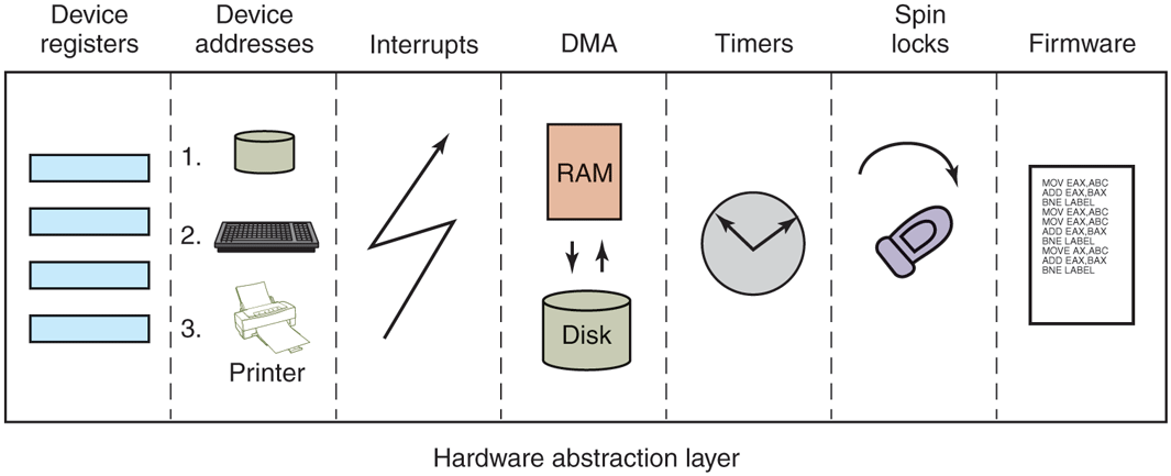
Some of the hardware functions the HAL manages.
The Kernel Layer
Above the hardware abstraction layer is NTOS, consisting of two layers: the kernel and the executive. ‘‘Kernel’’ is a confusing term in Windows. It can refer to all the code that runs in the processor’s kernel mode. It can also refer to the ntoskrnl.exe file which contains NTOS, the core of the Windows operating system. Or it can refer to the kernel layer within NTOS, which is how we use it in this section. It is even used to name the user-mode Win32 library that provides the wrappers for the native system calls: kernelbase.dll.
In the Windows operating system, the kernel layer, illustrated above the executive layer in Fig. 11-11, provides a set of abstractions for managing the CPU. The most central abstraction is threads, but the kernel also implements exception handling, traps, and several kinds of interrupts. Creating and destroying the data structures which support threading is implemented in the executive layer. The kernel layer is responsible for scheduling and synchronization of threads. Having support for threads in a separate layer allows the executive layer to be implemented using the same preemptive multithreading model used to write concurrent code in user mode, though the synchronization primitives in the executive are much more specialized.
The kernel’s thread scheduler is responsible for determining which thread is executing on each CPU in the system. Each thread executes until a timer interrupt signals that it is time to switch to another thread (quantum expired), or until the thread needs to wait for something to happen, such as an I/O to complete or for a lock to be released, or a higher-priority thread becomes runnable and needs the CPU. When switching from one thread to another, the scheduler runs on the CPU and ensures that the registers and other hardware state have been saved. The scheduler then selects another thread to run on the CPU and restores the state that was previously saved from the last time that thread ran.
If the next thread to be run is in a different address space (i.e., process) than the thread being switched from, the scheduler must also change address spaces. The details of the scheduling algorithm itself will be discussed later in this chapter when we come to processes and threads.
In addition to providing a higher-level abstraction of the hardware and handling thread switches, the kernel layer also has another key function: providing low-level support for two classes of synchronization mechanisms: control objects and dispatcher objects. Control objects are the data structures that the kernel layer provides as abstractions to the executive layer for managing the CPU. They are allocated by the executive but they are manipulated with routines provided by the kernel layer. Dispatcher objects are the class of ordinary executive objects that use a common data structure for synchronization.
Deferred Procedure Calls
Control objects include primitive objects for threads, interrupts, timers, synchronization, profiling, and two special objects for implementing DPCs (Deferred Procedure Calls) and APCs (see below). DPC objects are used to reduce the time taken to execute ISRs (Interrupt Service Routines) in response to an interrupt from a particular device. Limiting time spent in ISRs reduces the chance of losing an interrupt.
The system hardware assigns a hardware priority level to interrupts. The CPU also associates a priority level with the work it is performing. The CPU responds only to interrupts at a higher-priority level than it is currently using. Normal priority level, including the priority level of all user-mode work, is 0. Device interrupts occur at priority 3 or higher, and the ISR for a device interrupt normally executes at the same priority level as the interrupt in order to keep other less important interrupts from occurring while it is processing a more important one.
If an ISR executes too long, the servicing of lower-priority interrupts will be delayed, perhaps causing data to be lost or slowing the I/O throughput of the system. Multiple ISRs can be in progress at any one time, with each successive ISR being due to interrupts at higher and higher-priority levels.
To reduce the time spent processing ISRs, only the critical operations are performed, such as capturing the result of an I/O operation and reinitializing the device. Further processing of the interrupt is deferred until the CPU priority level is lowered and no longer blocking the servicing of other interrupts. The DPC object is used to represent the further work to be done and the ISR calls the kernel layer to queue the DPC to the list of DPCs for a particular processor. If the DPC is the first on the list, the kernel registers a special request with the hardware to interrupt the CPU at priority 2 (which NT calls DISPATCH level). When the last of any executing ISRs completes, the interrupt level of the processor will drop back below 2, and that will unblock the interrupt for DPC processing. The ISR for the DPC interrupt will process each of the DPC objects that the kernel had queued.
The technique of using software interrupts to defer interrupt processing is a well-established method of reducing ISR latency. UNIX and other systems started using deferred processing in the 1970s to deal with the slow hardware and limited buffering of serial connections to terminals. The ISR would deal with fetching characters from the hardware and queuing them. After all higher-level interrupt processing was completed, a software interrupt would run a low-priority ISR to do character processing, such as implementing backspace by sending control characters to the terminal to erase the last character displayed and move the cursor back.
A similar example in Windows today is the keyboard device. After a key is struck, the keyboard ISR reads the key code from a register and then reenables the keyboard interrupt but does not do further processing of the key immediately. Instead, it uses a DPC to queue the processing of the key code until all outstanding device interrupts have been processed.
Because DPCs run at level 2, they do not keep device ISRs from executing, but they do prevent any threads from running on that processor until all the queued DPCs complete and the CPU priority level is lowered below 2. Device drivers and the system itself must take care not to run either ISRs or DPCs for too long. Because threads are not allowed to execute, ISRs and DPCs can make the system appear sluggish and produce glitches when playing music by stalling the threads writing the music buffer to the sound device. Another common use of DPCs is running routines in response to a timer interrupt. To avoid blocking threads, timer events which need to run for an extended time should queue requests to the pool of worker threads the kernel maintains for background activities.
The problem of thread starvation due to excessively long or frequent DPCs (called DPC Storms) is common enough that Windows implements a defense mechanism called the DPC Watchdog. The DPC Watchdog has time limits for individual DPCs and for back-to-back DPCs. When these limits are exceeded, the watchdog issues a system crash with the DPC_WATCHDOG_VIOLATION code and information about the long DPC (typically a buggy driver) along with a crash dump which can help diagnose the issue.
Even though DPC storms are undesirable, so are system crashes. In environments like the Azure Cloud where DPC storms due to incoming network packets are relatively common and system crashes are catastrophic, DPC watchdog timeouts are typically configured higher to avoid crashes. To improve diagnosability in such situations, the DPC watchdog in Windows 11 supports soft and profiling thresholds. When the soft threshold is crossed, instead of crashing the system, the watchdog instead logs information which can later be analyzed to determine the source of the DPCs. When the profiling threshold is crossed, the watchdog starts a profiling timer and logs a stack trace of DPC execution every millisecond such that much more detailed analysis can be performed to understand the root cause of long or frequent DPCs.
In addition to the improved DPC watchdog, the Windows 11 thread scheduler is also smarter about reducing thread starvation in the face of DPCs. For each recent DPC, it maintains a short history of DPC runtime which is used to identify long-running DPCs. When such long-running DPCs are queued up on a processor, the currently-running thread (which is about to be starved) is rescheduled to another available processor if the thread is high-enough priority. This way, time-critical threads like those feeding media devices are much less likely to be starved due to DPCs.
Asynchronous Procedure Calls
The other special kernel control object is the APC (Asynchronous Procedure Call) object. APCs are like DPCs in that they defer processing of a system routine, but unlike DPCs, which operate in the context of particular CPUs, APCs execute in the context of a specific thread. When processing a key press, it does not matter which context the DPC runs in because a DPC is simply another part of interrupt processing, and interrupts only need to manage the physical device and perform thread-independent operations such as recording the data in a buffer in kernel space.
The DPC routine runs in the context of whatever thread happened to be running when the original interrupt occurred. It calls into the I/O system to report that the I/O operation has been completed, and the I/O system queues an APC to run in the context of the thread making the original I/O request, where it can access the user-mode address space of the thread that will process the input.
At the next convenient time, the kernel layer delivers the APC to the thread and schedules the thread to run. An APC is designed to look like an unexpected procedure call, somewhat similar to signal handlers in UNIX. The kernel-mode APC for completing I/O executes in the context of the thread that initiated the I/O, but in kernel mode. This gives the APC access to both the kernel-mode buffer as well as all of the user-mode address space belonging to the process containing the thread. When an APC is delivered depends on what the thread is already doing, and even what type of system. In a multiprocessor system, the thread receiving the APC may begin executing even before the DPC finishes running.
User-mode APCs can also be used to deliver notification of I/O completion in user mode to the thread that initiated the I/O. User-mode APCs invoke a user-mode procedure designated by the application, but only when the target thread has blocked in the kernel and is marked as willing to accept APCs, a state known as an alertable wait. The kernel interrupts the thread from waiting and returns to user mode, but with user-mode stack and registers modified to run the APC dispatch routine in the ntdll.dll system library. The APC dispatch routine invokes the usermode routine that the application has associated with the I/O operation. Besides specifying user-mode APCs as a means of executing code when I/Os complete, the Win32 API QueueUserAPC allows APCs to be used for arbitrary purposes.
Special User-mode APCs are a flavor of APC that were introduced in later Windows 10 releases. These are different from ‘‘normal’’ user-mode APCs in that they are completely asynchronous: they can execute even when the target thread is not in an alertable wait state. As such, special user APCs are the equivalent of UNIX signals, available to developers via the QueueUserAPC2 API. Prior to the advent of special user APCs, developers who needed to run code in arbitrary threads (e.g., for garbage collection in a managed runtime) had to resort to using more complicated mechanisms like manually changing the context of the target thread using SetThreadContext.
The executive layer also uses APCs for operations other than I/O completion. Because the APC mechanism is carefully designed to deliver APCs only when it is safe to do so, it can be used to safely terminate threads. If it is not a good time to terminate the thread, the thread will have declared that it was entering a critical region and defer deliveries of APCs until it leaves. Kernel threads mark themselves as entering critical regions to defer APCs when acquiring locks or other resources, so that they cannot be terminated while still holding the resource or deadlock due to reentrancy. The thread termination APC is very similar to a special user-mode APC except that it is ‘‘extra special’’ because it runs before any special user APC to terminate the thread immediately.
Dispatcher Objects
Another kind of synchronization object is the dispatcher object. This is any ordinary kernel-mode object (the kind that users can refer to with handles) that contains a data structure called a dispatcher_header, shown in Fig. 11-13. These objects include semaphores, mutexes, events, waitable timers, and other objects that threads can wait on to synchronize execution with other threads. They also include objects representing open files, processes, threads, and IPC ports. The dispatcher data structure contains a flag representing the signaled state of the object, and a queue of threads waiting for the object to be signaled.
Figure 11-13
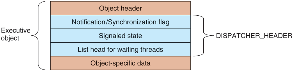
Dispatcher_header data structure embedded in many executive objects (dispatcher objects).
Synchronization primitives, like semaphores, are natural dispatcher objects. Also timers, files, ports, threads, and processes use the dispatcher-object mechanisms in order to do notifications. When a timer goes off, I/O completes on a file, data are available on a port, or a thread or process terminates, the associated dispatcher object is signaled, waking all threads waiting for that event.
Since Windows uses a single unified mechanism for synchronization with kernel-mode objects, specialized APIs, such as wait3, for waiting for child processes in UNIX, are not needed to wait for events. Often threads want to wait for multiple events at once. In UNIX a process can wait for data to be available on any of 64 network sockets using the select system call. In Windows, there is a similar API WaitForMultipleObjects, but it allows for a thread to wait on any type of dispatcher object for which it has a handle. Up to 64 handles can be specified to WaitForMultipleObjects, as well as an optional timeout value. The thread becomes ready to run whenever any of the events associated with the handles is signaled or the timeout occurs.
There are actually two different procedures the kernel uses for making the threads waiting on a dispatcher object runnable. Signaling a notification object will make every waiting thread runnable. Synchronization objects make only the first waiting thread runnable and are used for dispatcher objects that implement locking primitives, like mutexes. When a thread that is waiting for a lock begins running again, the first thing it does is to retry acquiring the lock. If only one thread can hold the lock at a time, all the other threads made runnable might immediately block, incurring lots of unnecessary context switching. The difference between dispatcher objects using synchronization vs. notification is a flag in the dispatcher_header structure.
As a little aside, mutexes in Windows are called ‘‘mutants’’ in the code because they were required to implement the OS/2 semantics of not automatically unlocking themselves when a thread holding one exited, something Cutler considered bizarre.
The Executive Layer
As shown in Fig. 11-11, below the kernel layer of NTOS there is the executive. The executive layer is written in C, is mostly architecture independent (the memory manager being a notable exception), and has been ported with only modest effort to new processors (MIPS, x86, PowerPC, Alpha, IA64, x64, arm32, and arm64). The executive contains a number of different components, all of which run using the control abstractions provided by the kernel layer.
Each component is divided into internal and external data structures and interfaces. The internal aspects of each component are hidden and used only within the component itself, while the external aspects are available to all the other components within the executive. A subset of the external interfaces are exported from the ntoskrnl.exe executable and device drivers can link to them as if the executive were a library. Microsoft calls many of the executive components ‘‘managers,’’ because each is charge of managing some aspect of the operating services, such as I/O, memory, processes, and objects.
As with most operating systems, much of the functionality in the Windows executive is like library code, except that it runs in kernel mode so its data structures can be shared and protected from access by user-mode code, and so it can access kernel-mode state, such as the MMU control registers. But otherwise the executive is simply executing operating system functions on behalf of its caller, and thus runs in the thread of its caller. This is the same as in UNIX systems.
When any of the executive functions block waiting to synchronize with other threads, the user-mode thread is blocked, too. This makes sense when working on behalf of a particular user-mode thread, but it can be unfair when doing work related to common housekeeping tasks. To avoid hijacking the current thread when the executive determines that some housekeeping is needed, a number of kernel-mode threads are created when the system boots and dedicated to specific tasks, such as making sure that modified pages get written to disk.
For predictable, low-frequency tasks, there is a thread that runs once a second and has a laundry list of items to handle. For less predictable work, there is the pool of high-priority worker threads mentioned earlier which can be used to run bounded tasks by queuing a request and signaling the synchronization event that the worker threads are waiting on.
The object manager manages most of the interesting kernel-mode objects used in the executive layer. These include processes, threads, files, semaphores, I/O devices and drivers, timers, and many others. As described previously, kernelmode objects are really just data structures allocated and used by the kernel. In Windows, kernel data structures have enough in common that it is very useful to manage many of them in a unified facility.
The facilities provided by the object manager include managing the allocation and freeing of memory for objects, quota accounting, supporting access to objects using handles, maintaining reference counts for kernel-mode pointer references as well as handle references, giving objects names in the NT namespace, and providing an extensible mechanism for managing the lifecycle for each object. Kernel data structures which need some of these facilities are managed by the object manager.
Object-manager objects each have a type which is used to specify exactly how the lifecycle of objects of that type is to be managed. These are not types in the object-oriented sense, but are simply a collection of parameters specified when the object type is created. To create a new type, an executive component calls an object-manager API to create a new type. Objects are so central to the functioning of Windows that the object manager will be discussed in more detail in the next section.
The I/O manager provides the framework for implementing I/O device drivers and provides a number of executive services specific to configuring, accessing, and performing operations on devices. In Windows, device drivers not only manage physical devices but they also provide extensibility to the operating system. Many functions that are hard compiled into the kernel on other systems are dynamically loaded and linked by the kernel on Windows, including network protocol stacks and file systems.
Recent versions of Windows have a lot more support for running device drivers in user mode, and this is the preferred model for new device drivers. There are hundreds of thousands of different device drivers for Windows working with more than a million distinct devices. This represents a lot of code to get correct. It is much better if bugs cause a device to become inaccessible by crashing in a usermode process rather than causing the system to crash. Bugs in kernel-mode device drivers are the major source of the dreaded BSOD (Blue Screen Of Death) where Windows detects a fatal error within kernel mode and shuts down or reboots the system. BSOD’s are comparable to kernel panics on UNIX systems.
Since device drivers make up something in the vicinity of 70% of the code in the kernel, the more drivers that can be moved into user-mode processes, where a bug will only trigger the failure of a single driver (rather than bringing down the entire system), the better. The trend of moving code from the kernel to user-mode processes for improved system reliability has been accelerating in recent years.
The I/O manager also includes the plug-and-play and device power-management facilities. Plug-and-play comes into action when new devices are detected on the system. The plug-and-play subcomponent is first notified. It works with a service, the user-mode plug-and-play manager, to find the appropriate device driver and load it into the system. Getting the right one is not always easy and sometimes depends on sophisticated matching of the specific hardware device version to a particular version of the drivers. Sometimes a single device supports a standard interface which is supported by multiple different drivers, written by different companies.
We will study I/O further in Sec. 11.7 and the most important NT file system, NTFS, in Sec. 11.8.
Device power management reduces power consumption when possible, extending battery life on notebooks, and saving energy on desktops and servers. Getting power management correct can be challenging as there are many subtle dependencies between devices and the buses that connect them to the CPU and memory. Power consumption is not affected just by what devices are powered-on, but also by the clock rate of the CPU, which is also controlled by the device power manager. We will take a more in-depth look at power management in Sec. 11.9.
The process manager manages the creation and termination of processes and threads, including establishing the policies and parameters which govern them. But the operational aspects of threads are determined by the kernel layer, which controls scheduling and synchronization of threads, as well as their interaction with the control objects, like APCs. Processes contain threads, an address space, and a handle table containing the handles the process can use to refer to kernel-mode objects. Processes also include information needed by the scheduler for switching between address spaces and managing process-specific hardware information (like segment descriptors). We will study process and thread management in Sec. 11.4.
The executive memory manager implements the demand-paged virtual memory architecture. It manages the mapping of virtual pages onto physical page frames, the management of the available physical frames, and management of the pagefile on disk used to back private instances of virtual pages that are no longer loaded in memory. The memory manager also provides special facilities for large server applications such as databases and programming language runtime components such as garbage collectors. We will study memory management later in this chapter, in Sec. 11.5.
The cache manager optimizes the performance of I/O to the file system by maintaining a cache of file-system pages in the kernel virtual address space. The cache manager uses virtually addressed caching, that is, organizing cached pages in terms of their location in their files. This differs from physical block caching, as in UNIX, where the system maintains a cache of the physically addressed blocks of the raw disk volume.
Cache management is implemented using mapped files. The actual caching is performed by the memory manager. The cache manager need be concerned only with deciding what parts of what files to cache, ensuring that cached data is flushed to disk in a timely fashion, and managing the kernel virtual addresses used to map the cached file pages. If a page needed for I/O to a file is not available in the cache, the page will be faulted in using the memory manager. We will study the cache manager in Sec. 11.6.
The security reference monitor enforces Windows’ elaborate security mechanisms, which support the international standards for computer security called Common Criteria, an evolution of United States Department of Defense Orange Book security requirements. These standards specify a large number of rules that a conforming system must meet, such as authenticated login, auditing, zeroing of allocated memory, and many more. One rules requires that all access checks be implemented by a single module within the system. In Windows, this module is the security reference monitor in the kernel. We will study the security system in more detail in Sec. 11.10.
The executive contains a number of other components that we will briefly describe. The configuration manager is the executive component which implements the registry, as described earlier. The registry contains configuration data for the system in file-system files called hives. The most critical hive is the SYSTEM hive which is loaded into memory every time the system is booted from disk. Only after the executive layer has successfully initialized all of its key components, including the I/O drivers that talk to the system disk, is the in-memory copy of the hive reassociated with the copy in the file system. Thus, if something bad happens while trying to boot the system, the on-disk copy very unlikely to be corrupted. If the on-disk copy were to be corrupted, that would be a disaster.
The local procedure call component provides for a highly efficient interprocess communication used between processes running on the same system. It is one of the data transports used by the standards-based remote procedure call facility to implement the client/server style of computing. RPC also uses named pipes and TCP/IP as transports.
LPC was substantially enhanced in Windows 8 (it is now called ALPC, (Advanced LPC) to provide support for new features in RPC, including RPC from kernel mode components, like drivers. LPC was a critical component in the original design of NT because it is used by the subsystem layer to implement communication between library stub routines that run in each process and the subsystem process which implements the facilities common to a particular operating system personality, such as Win32 or POSIX.
Windows also provides a publish/subscribe service called WNF (Windows Notification Facility). WNF notifications are based on changes to an instance of WNF state data. A publisher declares an instance of state data (up to 4 KB) and tells the operating system how long to maintain it (e.g., until the next reboot or permanently). A publisher atomically updates the state as appropriate. Subscribers can arrange to run code whenever an instance of state data is modified by a publisher. Because the WNF state instances contain a fixed amount of preallocated data, there is no queuing of data as in message-based IPC—with all the attendant resource-management problems. Subscribers are guaranteed only that they can see the latest version of a state instance.
This state-based approach gives WNF its principal advantage over other IPC mechanisms: publishers and subscribers are decoupled and can start and stop independently of each other. Publishers need not execute at boot time just to initialize their state instances, as those can be persisted by the operating system across reboots. Subscribers generally need not be concerned about past values of state instances when they start running as all they should need to know about the state’s history is encapsulated in the current state. In scenarios where past state values cannot be reasonably encapsulated, the current state can provide metadata for managing historical state, say, in a file or in a persisted section object used as a circular buffer. WNF is part of the native NT APIs and is not (yet) exposed via Win32 interfaces. But it is extensively used internally by the system to implement Win32 and WinRT APIs.
In Windows NT 4.0, much of the code related to the Win32 graphical interface was moved into the kernel because the then-current hardware could not provide the required performance. This code previously resided in the csrss.exe subsystem process which implemented the Win32 interfaces. The kernel-based GUI code resides in a special kernel-driver, win32k.sys. The move to kernel-mode improved Win32 performance because the extra user-mode/kernel-mode transitions and the cost of switching address spaces to implement communication via LPC was eliminated. However, it has not been without problems because the security requirements on code running in the kernel are very strict, and the complicated API interface exposed by win32k to user-mode has resulted in numerous security vulnerabilities. A future Windows release will hopefully move win32k back into a usermode process while maintaining acceptable performance for GUI code.
The Device Drivers
The final part of Fig. 11-11 consists of the device drivers. Device drivers in Windows are dynamic link libraries which are loaded by the NTOS executive. Though they are primarily used to implement the drivers for specific hardware, such as physical devices and I/O buses, the device-driver mechanism is also used as the general extensibility mechanism for kernel mode. As described earlier, much of the Win32 subsystem is loaded as a driver.
The I/O manager organizes a data flow path for each instance of a device, as shown in Fig. 11-14. This path is called a device stack and consists of private instances of kernel device objects allocated for the path. Each device object in the device stack is linked to a particular driver object, which contains the table of routines to use for the I/O request packets that flow through the device stack. In some cases, the devices in the stack represent drivers whose sole purpose is to filter I/O operations aimed at a particular device, bus, or network driver. Filtering is used for a number of reasons. Sometimes preprocessing or postprocessing I/O operations results in a cleaner architecture, while other times it is just pragmatic because the sources or rights to modify a driver are not available and so filtering is used to work around the inability to modify those drivers. Filters can also implement completely new functionality, such as turning disks into partitions or multiple disks into RAID volumes.
Figure 11-14
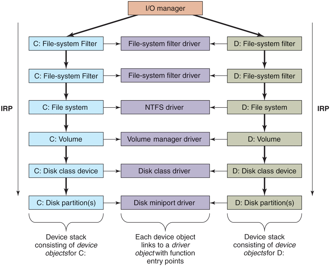
Simplified depiction of device stacks for two NTFS file volumes. The I/O request packet is passed from down the stack. The appropriate routines from the associated drivers are called at each level in the stack. The device stacks themselves consist of device objects allocated specifically to each stack.
The file systems are loaded as device drivers. Each instance of a volume for a file system has a device object created as part of the device stack for that volume. This device object will be linked to the driver object for the file system appropriate to the volume’s formatting. Special filter drivers, called file-system filter drivers, can insert device objects before the file-system device object to apply functionality to the I/O requests being sent to each volume, such as handling encryption.
The network protocols, such as Windows’ integrated IPv4/IPv6 TCP/IP implementation, are also loaded as drivers using the I/O model. For compatibility with the older MS-DOS-based Windows, the TCP/IP driver implements a special protocol for talking to network interfaces on top of the Windows I/O model. There are other drivers that also implement such arrangements, which Windows calls miniports. The shared functionality is in a class driver. For example, common functionality for SCSI or IDE disks or USB devices is supplied by a class driver, which miniport drivers for each particular type of such devices link to as a library.
We will not discuss any particular device driver in this chapter, but will provide more detail about how the I/O manager interacts with device drivers in Sec. 11.7.
11.3.2 Booting Windows
Getting an operating system to run requires several steps. When a computer is turned on, the first processor is initialized by the hardware, and then set to start executing some program in memory. The only available code is in some form of nonvolatile CMOS memory that is initialized by the computer manufacturer (and sometimes updated by the user, in a process called flashing). Because the software persists in (read-only) memory, and is only rarely updated, it is referred to as firmware. It is held in a special chip whose contents are not lost when power is turned off. The firmware is loaded on PCs by the manufacturer of either the motherboard or the computer system. Historically, PC firmware was a program called BIOS (Basic Input/Output System), but most new computers use UEFI (Unified Extensible Firmware Interface). UEFI improves over BIOS by supporting modern hardware, providing a more modular CPU-independent architecture, much improved security mechanisms and supporting an extension model which simplifies booting over networks, provisioning new machines, and running diagnostics. Windows 11 supports only UEFI-based machines.
The main purpose of any firmware is to bring up the operating system by locating and running the bootstrap application. UEFI firmware achieves this by first requiring that the boot disk be formatted in the GPT (GUID partition table) scheme where each disk partition is identified by a GUID (Globally-Unique IDentifier), which, in practice, is a 128-bit number generated to ensure uniqueness. The Windows setup program initializes the boot disk in the GPT format and creates several partitions. The most important are the EFI system partition which is formatted with FAT32 and contains the Windows Boot Manager UEFI application (bootmgrfw.efi) and the boot partition which is formatted with NTFS and contains the actual Windows installation. In addition, the setup program sets some well-known UEFI global variables that indicate to the firmware the location of Windows Boot Manager. These variables are stored in the system’s nonvolatile memory and persist across boots.
Given a GPT-partitioned disk, the UEFI firmware locates the Windows Boot Manager in the EFI system partition and transfers control to it. It’s able to do this because the firmware supports the FAT32 file system (but not the NTFS file system). The boot manager’s job is to select the appropriate OS loader application and execute it. The OS loader’s job is to load the actual operating system files into memory and start running the OS. Both the boot manager and the OS loader rely on the UEFI firmware facilities for basic memory management, disk I/O, textual and graphical console I/O. However, once all the required operating system files are loaded into memory and prepared for execution, ‘‘ownership’’ of the platform is transferred to the operating system kernel and these boot services provided by the firmware are discarded from memory. The kernel then initializes its own storage and file system drivers to mount the boot partition and load the rest of the files necessary to boot Windows.
Boot security is the foundation of OS security. The boot sequence must be protected from a special type of malware called rootkits which are sophisticated malicious software that inject themselves into the boot sequence, take control of the hardware, and hide themselves from the security mechanisms that load afterwards (such as anti-malware applications). As a countermeasure, UEFI supports a feature called Secure Boot which validates the integrity of every component loaded during the boot process including the UEFI firmware itself. This verification is performed by checking the digital signature of each component against a database of trusted certificates (or certificates issued by trusted certificates), thereby establishing a chain of trust rooted at the root certificate. As part of Secure Boot, the firmware validates the Windows Boot Manager before transferring control to it, which, then validates the OS loader, which, then validates the operating system files (hypervisor, secure kernel, kernel, boot drivers, and so on).
Digital signature verification involves calculating a cryptographic hash for the component to be verified. This hash value is also measured into the TPM (Trusted Platform Module) which is a secure cryptographic processor required to be present by Windows 11. The TPM provides various security services such as protection of encryption keys, boot measurements, and attestation. The act of measuring a hash value into the TPM cryptographically combines the hash value with the existing value in a PCR (Platform Configuration Register) in an operation called extending the PCR. The Windows Boot Manager and the OS loader measure not only the hashes of components to be executed, but also important pieces of boot configuration such as the boot device, code signing requirements, and whether debugging is enabled. The TPM does not allow the PCR values to be manipulated in any way other than extending. As a result, PCRs provide a tamper-proof mechanism to record the OS boot sequence. This is called Measured Boot. Injection of a rootkit or a change in boot configuration will result in a different final PCR value. This property allows the TPM to support two important scenarios:
Attestation. Organizations may want to ensure that a computer is free of rootkits before allowing it access to the enterprise network. A trusted remote attestation server can request from each client a TPM Quote which is a signed collection of PCR values that can be checked against a database of acceptable values to determine whether the client is healthy.
Sealing. The TPM supports storing a secret key using PCR values such that it can be unsealed in a later boot session only if those PCRs have the same values. The BitLocker volume encryption solution uses the boot sequence PCR values to seal its encryption key into the TPM such that the key can only be revealed if the boot sequence is not tampered with.
The Windows Boot Manager orchestrates the steps to boot Windows. It first loads from the EFI system partition the BCD (Boot Configuration Database) which is registry hive containing descriptors for all boot applications and their parameters. It then checks whether the system had previously been hibernated (a special power-saving mode where the operating system state is saved to disk). If so, the boot manager runs the winresume.efi boot application which ‘‘resumes’’ Windows from the saved snapshot. Otherwise, it loads and executes the OS loader boot application, winload.efi, to perform a fresh boot. Both of these UEFI applications are generally located on the NTFS-formatted boot volume. The boot manager understands a wide selection of file system formats in order to support booting from various devices. Also, since the boot volume may be encrypted with BitLocker, the boot manager must request the TPM to unseal the BitLocker volume decryption key in order to access winresume or winload.
The Windows OS loader is responsible for loading the remaining boot components into memory: the hypervisor loader (hvloader.dll), the secure kernel (securekernel.exe), the NT kernel/executive/HAL (ntoskrnl.exe), the stub HAL (hal.dll), the SYSTEM hive as well as all boot drivers listed in the SYSTEM hive. It executes the hypervisor loader which picks the appropriate hypervisor binary based on the underlying system and starts it. Then the Secure Kernel is initialized and finally, winload transfers control to the NT Kernel entry point. NT Kernel initialization happens in several phases. Phase 0 initialization runs on the boot processor and initializes the processor structures, locks, kernel address space, and data structures of kernel components. Phase 1 starts all the remaining processors and completes final initialization of all kernel components. At the end of Phase 1, once the I/O manager is initialized, boot drivers are started and file systems are mounted, the rest of OS boot can proceed to load new binaries from disk.
The first user-mode process to get started during boot is smss.exe which is similar to /etc/init in UNIX systems. Smss first completes the initialization of the subsystem-independent parts of the operating system by creating any configured paging files and finalizing registry initialization by loading the remaining hives. Then it starts acting as a session manager: it launches new instances of itself to initialize Session 0, the non-interactive session, and Session 1, the interactive session. These child smss instances are responsible for enumerating and starting NT subsystems which are listed under the HKLM\ SYSTEM\ CurrentControlSet\ Control\ Session Manager\ Subsystems registry key. On Windows 11, the only supported subsystem is the Windows subsystem, so the child smss instance starts the Windows subsystem process, csrss.exe. Then the Session 0 instance executes the wininit.exe process to initialize the rest of the Windows subsystem while the Session 1 instance starts the winlogon.exe process to allow the interactive user to log in.
The Windows boot sequence has logic to deal with common problems users encounter when booting the system fails. Sometimes installation of a bad device driver, or incorrectly modifying the SYSTEM hive can prevent the system from booting successfully. To recover from these situations, Windows boot manager allows users to launch the WinRE (Windows Recovery Environment) WinRE provides an assortment of tools and automated repair mechanisms. These include System Restore which allows restoring the boot volume to a previous snapshot. Another is Startup Repair which is an automated tool that detects and fixes the most common sources of startup problems. PC Reset performs the equivalent of a factory reset to bring Windows back to its original state after installation. For cases where manual intervention may be necessary, WinRE can also launch a command prompt where the user has access to any command-line tool. Similarly, the system may be booted in safe-mode where only a minimal set of device drivers and services are loaded to minimize the chances of encountering startup failure.
11.3.3 Implementation of the Object Manager
The object manager is probably the single most important component in the Windows executive, which is why we have already introduced many of its concepts. As described earlier, it provides a uniform and consistent interface for managing system resources and data structures, such as open files, processes, threads, memory sections, timers, devices, drivers, and semaphores. Even more specialized objects representing things like kernel transactions, profiles, security tokens, and Win32 desktops are managed by the object manager. Device objects link together the descriptions of the I/O system, including providing the link between the NT namespace and file-system volumes. The configuration manager uses an object of type key to link in the registry hives. The object manager itself has objects it uses to manage the NT namespace and implement objects using a common facility. These are directory, symbolic link, and object-type objects.
The uniformity provided by the object manager has various facets. All these objects use the same mechanism for how they are created, destroyed, and accounted for in the quota system. They can all be accessed from user-mode processes using handles. There is a unified convention for managing pointer references to objects from within the kernel. Objects can be given names in the NT namespace (which is managed by the object manager). Dispatcher objects (objects that begin with the common data structure for signaling events) can use common synchronization and notification interfaces, like WaitForMultipleObjects. There is the common security system with ACLs enforced on objects opened by name, and access checks on each use of a handle. There are even facilities to help kernel-mode developers debug problems by tracing the use of objects.
A key to understanding objects is to realize that an (executive) object is just a data structure in the virtual memory accessible to kernel mode. These data structures are commonly used to represent more abstract concepts. As examples, executive file objects are created for each instance of a file-system file that has been opened. Process objects are created to represent each process. Communication objects (e.g., semaphores) are another example.
A consequence of the fact that objects are just kernel data structures is that when the system is rebooted (or crashes) all objects are lost. When the system boots, there are no objects present at all, not even the object-type descriptors. All object types, and the objects themselves, have to be created dynamically by other components of the executive layer by calling the interfaces provided by the object manager. When objects are created and a name is specified, they can later be referenced through the NT namespace. So building up the objects as the system boots also builds the NT namespace.
Objects have a structure, as shown in Fig. 11-15. Each object contains a header with certain information common to all objects of all types. The fields in this header include the object’s name, the object directory in which it lives in the NT namespace, and a pointer to a security descriptor representing the ACL for the object.
Figure 11-15
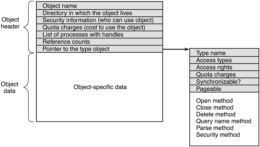
Structure of an executive object managed by the object manager.
The memory allocated for objects comes from one of two heaps (or pools) of memory maintained by the executive layer. There are (malloc-like) utility functions in the executive that allow kernel-mode components to allocate either pageable or non-pageable kernel memory. Non-pageable memory is required for any data structure or kernel-mode object that might need to be accessed from a CPU interrupt request level of 2 or more. This includes ISRs and DPCs (but not APCs) and the thread scheduler itself. The page-fault handler and the paging path through the file system and storage drivers also require their data structures to be allocated from non-pageable kernel memory to avoid recursion.
Most allocations from the kernel heap manager are achieved using per-processor lookaside lists which contain LIFO lists of allocations the same size. These LIFOs are optimized for lock-free operation, improving the performance and scalability of the system.
Each object header contains a quota-charge field, which is the charge levied against a process for opening the object. Quotas are used to keep a user from using too many system resources. On a personal notebook that doesn’t matter but on a shared server, it does. There are separate limits for non-pageable kernel memory (which requires allocation of both physical memory and kernel virtual addresses) and pageable kernel memory (which uses up kernel virtual addresses and pagefile space). When the cumulative charges for either memory type hit the quota limit, allocations for that process fail due to insufficient resources. Quotas also are used by the memory manager to control working-set size, and by the thread manager to limit the rate of CPU usage.
Both physical memory and kernel virtual addresses are extremely valuable resources. When an object is no longer needed, it should be deleted and its memory and addresses reclaimed to free up important resources. But it is important that an object should only be deleted when it is no longer in use. In order to correctly track object lifetime, the object manager implements a reference counting mechanism and the concept of a referenced pointer which is a pointer to an object whose reference count has been incremented for that pointer. This mechanism prevents premature object deletion when multiple asynchronous operations may be in flight on different threads. Generally, when the last reference to an object is dropped, the object is deleted. It is critical not to delete an object that is in use by some process.
Handles
User-mode references to kernel-mode objects cannot use pointers because they are too difficult to validate and, more importantly, user-mode does not have visibility into kernel-mode address-space layout due to security reasons. Instead, kernelmode objects must be referred to via an indirection layer. Windows uses handles to refer to kernel-mode objects. Handles are opaque values which are converted by the object manager into references to the specific kernel-mode data structure representing an object. Figure 11-16 shows the handle-table data structure used to translate handles into object pointers. The handle table is expandable by adding extra layers of indirection. Each process has its own table, including the system process which contains all the kernel threads not belonging to a user-mode process.
Figure 11-16
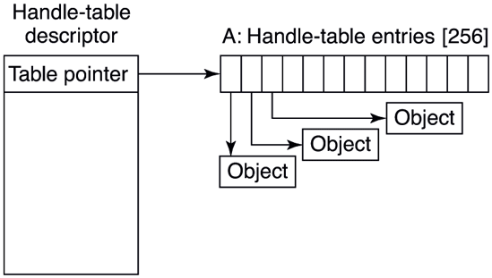
Handle table data structures for a minimal table using a single page for up to 512 handles.
Figure 11-17 shows a handle table with two extra levels of indirection, the maximum supported. It is sometimes convenient for code executing in kernel mode to be able to use handles rather than referenced pointers. These are called kernel handles and are specially encoded so that they can be distinguished from usermode handles. Kernel handles are kept in the system processes’ handle table and cannot be accessed from user mode. Just as most of the kernel virtual address space is shared across all processes, the system handle table is shared by all kernel components, no matter what the current user-mode process is.
Figure 11-17
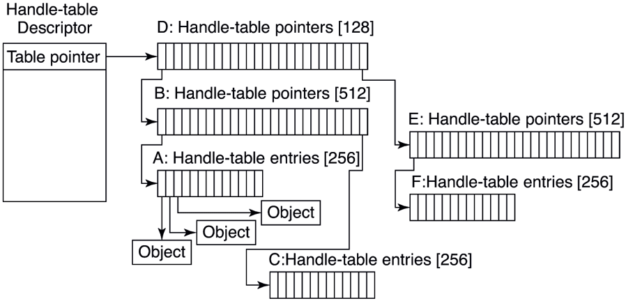
Handle-table data structures for a maximal table of up to 16 million handles.
Users can create new objects or open existing objects by making Win32 calls such as CreateSemaphore or OpenSemaphore. These are calls to library procedures that ultimately result in the appropriate system calls being made. The result of any successful call that creates or opens an object is a handle-table entry that is stored in the process’ private handle table in kernel memory. The 32-bit index of the handle’s logical position in the table is returned to the user to use on subsequent calls. The handle-table entry in the kernel contains a referenced pointer to the object, some flags (e.g., whether the handle should be inherited by child processes), and an access rights mask. The access rights mask is needed because permissions checking is done only at the time the object is created or opened. If a process has only read permission to an object, all the other rights bits in the mask will be 0s, giving the operating system the ability to reject any operation on the object other than reads.
In order to manage lifetime, the object manager keeps a separate handle count in every object. This count is never larger than the referenced pointer count because each valid handle has a referenced pointer to the object in its handle-table entry. The reason for the separate handle count is that many types of objects may need to have their state cleaned up when the last user-mode reference disappears, even though they are not yet ready to have their memory deleted.
One example is file objects, which represent an instance of an opened file. In Windows, files can be opened for exclusive access. When the last handle for a file object is closed, it is important to delete the exclusive access at that point rather than wait for any incidental kernel references to eventually go away (e.g., after the last flush of data from memory). Otherwise closing and reopening a file from user mode may not work as expected because the file still appears to be in use.
Though the object manager has comprehensive mechanisms for managing object lifetimes within the kernel, neither the NT APIs nor the Win32 APIs provide a reference mechanism for dealing with the use of handles across multiple concurrent threads in user mode. Thus, many multithreaded applications have race conditions and bugs where they will close a handle in one thread before they are finished with it in another. Or they may close a handle multiple times, or close a handle that another thread is still using and reopen it to refer to a different object.
Perhaps the Windows APIs should have been designed to require a close API per object type rather than the single generic NtClose operation. That would have at least reduced the frequency of bugs due to user-mode threads closing the wrong handles. Another solution might be to embed a sequence field in each handle in addition to the index into the handle table.
To help application writers find problems like these in their programs, Windows has an application verifier that software developers can download from Microsoft. Similar to the verifier for drivers we will describe in Sec. 11.7, the application verifier does extensive rules checking to help programmers find bugs that might not be found by ordinary testing. It can also turn on a FIFO ordering for the handle free list, so that handles are not reused immediately (i.e., turns off the better-performing LIFO ordering normally used for handle tables). Keeping handles from being reused quickly transforms situations where an operation uses the wrong handle into use of a closed handle, which is easy to detect.
The Object Namespace
Processes can share objects by having one process duplicate a handle to the object into the others. But this requires that the duplicating process have handles to the other processes, and is thus impractical in many situations, such as when the processes sharing an object are unrelated, or are protected from each other. In other cases, it is important that objects persist even when they are not being used by any process, such as device objects representing physical devices, or mounted volumes, or the objects used to implement the object manager and the NT namespace itself. To address general sharing and persistence requirements, the object manager allows arbitrary objects to be given names in the NT namespace when they are created. However, it is up to the executive component that manipulates objects of a particular type to provide interfaces that support use of the object manager’s naming facilities.
The NT namespace is hierarchical, with the object manager implementing directories and symbolic links. The namespace is also extensible, allowing any object type to specify extensions of the namespace by specifying a Parse routine. The Parse routine is one of the procedures that can be supplied for each object type when it is created, as shown in Fig. 11-18.
Figure 11-18
| Procedure | When called | Notes |
|---|---|---|
| Open | For every new handle | Rarely used |
| Parse | For object types that extend the namespace | Used for files and registry keys |
| Close | At last handle close | Clean up visible side effects |
| Delete | At last pointer dereference | Object is about to be deleted |
| Security | Get or set object’s security descriptor | Protection |
| QueryName | Get object’s name | Rarely used outside kernel |
Object procedures supplied when specifying a new object type.
The Open procedure is rarely used because the default object-manager behavior is usually what is needed and so the procedure is specified as NULL for almost all object types.
The Close and Delete procedures represent different phases of being done with an object. When the last handle for an object is closed, there may be actions necessary to clean up the state and these are performed by the Close procedure. When the final pointer reference is removed from the object, the Delete procedure is called so that the object can be prepared to be deleted and have its memory reused. With file objects, both of these procedures are implemented as callbacks into the I/O manager, which is the component that declared the file object type. The object-manager operations result in I/O operations that are sent down the device stack associated with the file object; the file system does most of the work.
The Parse procedure is used to open or create objects, like files and registry keys, that extend the NT namespace. When the object manager is attempting to open an object by name and encounters a leaf node in the part of the namespace it manages, it checks to see if the type for the leaf-node object has specified a Parse procedure. If so, it invokes the procedure, passing it any unused part of the path name. Again using file objects as an example, the leaf node is a device object representing a particular file-system volume. The Parse procedure is implemented by the I/O manager, and results in an I/O operation to the file system to fill in a file object to refer to an open instance of the file that the path name refers to on the volume. We will explore this particular example step-by-step below.
The QueryName procedure is used to look up the name associated with an object. The Security procedure is used to get, set, or delete the security descriptors on an object. For most object types, this procedure is supplied as a standard entry point in the executive’s security reference monitor component.
Note that the procedures in Fig. 11-18 do not perform the most useful operations for each type of object, such as read or write on files (or down and up on semaphores). Rather, the object manager procedures supply the functions needed to correctly set up access to objects and then clean up when the system is finished with them. The objects are made useful by the APIs that operate on the data structures the objects contain. System calls, like NtReadFile and NtWriteFile, use the process’ handle table created by the object manager to translate a handle into a referenced pointer on the underlying object, such as a file object, which contains the data that is needed to implement the system calls.
Apart from the object-type callbacks, the object manager also provides a set of generic object routines for operations like creating objects and object types, duplicating handles, getting a referenced pointer from a handle or name, adding and subtracting reference counts to the object header, and NtClose (the generic function that closes all types of handles).
Although the object namespace is crucial to the entire operation of the system, few people know that it even exists because it is not visible to users without special viewing tools. One such viewing tool is winobj, available for free at the URL https://www.microsoft.com/technet/sysinternals. When run, this tool depicts an object namespace that typically contains the object directories listed in Fig. 11-19 as well as a few others.
Figure 11-19
| Directory | Contents |
|---|---|
| \GLOBAL?? | Starting place for looking up Win32 devices like C: |
| \Device | All discovered I/O devices |
| \Driver | Objects corresponding to each loaded device driver |
| \ObjectTypes | The type objects such as those listed in Fig. 11-21 |
| \Windows | Objects for sending messages to all the Win32 GUI windows |
| \BaseNamedObjects | User-created Win32 objects such as events, mutexes, etc. |
| \Sessions | Win32 objects created in the session. Sess. 0 uses \BaseNamedObjects |
| \Arcname | Partition names discovered by the boot loader |
| \NLS | National Language Support objects |
| \FileSystem | File-system driver objects and file system recognizer objects |
| \Security | Objects belonging to the security system |
| \KnownDLLs | Key shared libraries that are opened early and held open |
Some typical directories in the object namespace.
The object manager namespace is not directly exposed through the Win32 API. In fact, Win32 namespace for devices and named objects does not even have a hierarchical structure. This allows the Win32 namespace to be mapped to the object manager namespace in creative ways to provide various application isolation scenarios.
The Win32 namespace for named objects is flat. For example, the CreateEvent function takes an optional object name parameter. This allows multiple applications to open the same underlying Event object and synchronize with one another as long as they agree on the event name, say ‘‘MyEvent.’’ The Win32 layer in usermode (kernelbase.dll) determines an object manager directory to place its named objects, called BaseNamedObjects. But, where in the object manager namespace should BaseNamedObjects live? If it is stored in a global location, the application sharing scenario is satisfied, but when multiple users are logged onto the machine, application instances in each session may interfere with one another since they expect to be manipulating their own event.
To solve this problem, the Win32 namespace for named objects is instanced per user session. Session 0 (where non-interactive OS services run) uses the toplevel \BaseNamedObjects directory and each interactive session has its own BaseNamedObjects directory underneath the top-level \Sessions directory. For example, if a Session 0 service calls CreateEvent with ‘‘MyEvent,’’ kernelbase.dll redirects it to \BaseNamedObjects\MyEvent, but if an application running in interactive Session 2 makes the same call, the event is \Sessions\2\BaseNamedObjects\MyEvent.
There may be instances where an application running in an interactive user session needs to share a named event with a Session 0 service. To accommodate that scenario, each session-local BaseNamedObjects directory contains a symbolic link, called Global, pointing to the top-level \BaseNamedObjects directory. That way, an application can call CreateEvent with ‘‘Global\MyEvent’’ to open \BaseNamedObjects\MyEvent. Similarly, sometimes a Session 0 service may need to open or create a named object in a particular user session. The BaseNamedObjects directory contains another symbolic link called Session which points to \Sessions\BNOLINKS. That directory, in turn, contains a symbolic link for each active session, pointing to that session’s BaseNamedObjects directory. Therefore, a Session 0 process can use the ‘‘Session\3\MyEvent’’ Win32 name to get redirected to \Sessions\3\BaseNamedObjects\MyEvent.
In the Universal Windows Platform section, we described how UWP apps run in a sandbox called an AppContainer. Namespace isolation for AppContainers is also achieved via BaseNamedObjects mapping. Each session, including Session 0, contains an AppContainerNamedObjects directory underneath \Sessions\<ID>. Each AppContainer has a dedicated directory here for its BaseNamedObjects whose name is derived from the UWP application’s package identity. This gives each UWP app its own isolated Win32 namespace. This arrangement also avoids the namespace squatting problem where a malicious application creates a named object that it knows its victim will open when it runs. Most Win32 API calls to create named objects will, by default, open the object if it already exists in order to facilitate sharing, but this behavior also allows a squatter to create the object first, even though it might not have had the required permissions to open the object had it been created by the victim application first.
So far we discussed how the Win32 named object namespace is mapped to the global namespace using object manager facilities. The Win32 device namespace also relies on the object manager for proper instancing and isolation. The interestingly named directory \GLOBAL?? shown in Fig. 11-19 contains all Win32 device names, such as A: for the floppy disk and C: for the first hard disk. These names are actually symbolic links to the \Device directory where the device objects live. For example, C: might be a symbolic link to \Device\ HarddiskVolume1.
Windows allows each user to map Win32 drive letters to devices such as local or remote volumes. Such mappings need to be kept local to that user session to avoid interfering with other users’ mappings. This is achieved, again, by instancing the object manager directory containing Win32 devices. Session-local device mappings are stored in the DosDevices directory for each session (e.g., \Sessions\1\DosDevices\Z:). The Win32 layer in user-mode always prepends \??\ to paths, indicating that these are Win32 device paths. The object manager has specific handling for items under the \?? directory: it first searches for the item in the session-local DosDevices directory associated with the calling process. If the item is not found, then the \GLOBAL?? directory is searched. For example, a CreateFile call for ‘‘C:’’ from a process in Session 2 will result in an NtCreateFile call to \??\ C: and the object manager will check \Sessions\2\DosDevices\CZ: followed by \GLOBAL??\C: to find the symbolic link.
Object Types
The device object is one of the most important and versatile kernel-mode objects in the executive. The type is specified by the I/O manager, which, along with the device drivers, are the primary users of device objects. Device objects are closely related to drivers, and each device object usually has a link to a specific driver object, which describes how to access the I/O processing routines for the driver corresponding to the device.
Device objects represent hardware devices, interfaces, and buses, as well as logical disk partitions, disk volumes, and even file systems and kernel extensions like antivirus filters. Many device drivers are given names, so they can be accessed without having to open handles to instances of the devices, as in UNIX. We will use device objects to illustrate how the Parse procedure is used, as illustrated in Fig. 11-20:
When an executive component, such as the I/O manager implementing the native system call
NtCreateFile, callsObOpenObjectByNamein the object manager, it passes a Unicode path name for the NT namespace, say \??\C:\foo\bar.The object manager searches through directories and symbolic links and ultimately finds that \??\C: refers to a device object (a type defined by the I/O manager). The device object is a leaf node in the part of the NT namespace that the object manager manages.
The object manager then calls the Parse procedure for this object type, which happens to be
IopParseDeviceimplemented by the I/O manager. It passes not only a pointer to the device object it found (for C:), but also the remaining string \foo\bar.The I/O manager will create an IRP (I/O Request Packet), allocate a file object, and send the request to the stack of I/O devices determined by the device object found by the object manager.
The IRP is passed down the I/O stack until it reaches a device object representing the file-system instance for C:. At each stage, control is passed to an entry point into the driver object associated with the device object at that level. The entry point used here is for CREATE operations, since the request is to create or open a file named \foo\bar on the volume.
The device objects encountered as the IRP heads toward the file system represent file-system filter drivers, which may modify the I/O operation before it reaches the file-system device object. Typically these intermediate devices represent system extensions like antivirus filters.
The file-system device object has a link to the file-system driver object, say NTFS. So, the driver object contains the address of the CREATE operation within NTFS.
NTFS will fill in the file object and return it to the I/O manager, which returns back up through all the devices on the stack until
IopParseDevicereturns to the object manager (see Sec. 11.8).The object manager is finished with its namespace lookup. It received back an initialized object from the Parse routine (which happens to be a file object—not the original device object it found). So the object manager creates a handle for the file object in the handle table of the current process and returns the handle to its caller.
The final step is to return back to the user-mode caller, which in this example is the Win32 API
CreateFile, which will return the handle to the application.
Figure 11-20
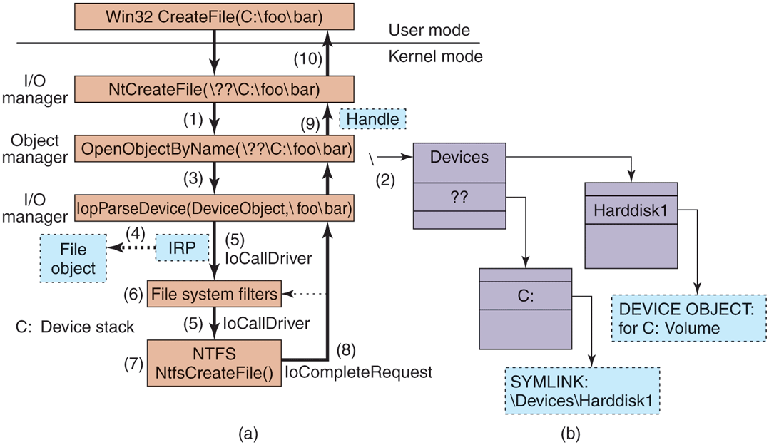
I/O and object manager steps for creating/opening a file and getting back a file handle.
Executive components can create new types dynamically, by calling the ObCreateObjectType interface to the object manager. There is no definitive list of object types and they change from release to release. Some of the more common ones in Windows are listed in Fig. 11-21. Let us briefly go over them.
Figure 11-21
| Type | Description |
|---|---|
| Process | User process |
| Thread | Thread within a process |
| Semaphore | Counting semaphore used for interprocess synchronization |
| Mutex | Binary semaphore used to enter a critical region |
| Event | Synchronization object with persistent state (signaled/not) |
| ALPC port | Mechanism for interprocess message passing |
| Timer | Object allowing a thread to sleep for a fixed time interval |
| Queue | Object used for completion notification on asynchronous I/O |
| Open file | Object associated with an open file |
| Access token | Security descriptor for some object |
| Profile | Data structure used for profiling CPU usage |
| Section | Object used for representing mappable files |
| Key | Registry key, used to attach registry to object-manager namespace |
| Object directory | Directory for grouping objects within the object manager |
| Symbolic link | Refers to another object manager object by path name |
| Device | I/O device object for a physical device, bus, driver, or volume instance |
| Device driver | Each loaded device driver has its own object |
Some common executive object types managed by the object manager.
Process and thread are obvious. There is one object for every process and every thread, which holds the main properties needed to manage the process or thread. The next three objects, semaphore, mutex, and event, all deal with interprocess synchronization. Semaphores and mutexes work as expected, but with various extra bells and whistles (e.g., maximum values and timeouts). Events can be in one of two states: signaled or nonsignaled. If a thread waits on an event that is in signaled state, the thread is released immediately. If the event is in nonsignaled state, it blocks until some other thread signals the event, which releases either all blocked threads (notification events) or just the first blocked thread (synchronization events). An event can also be set up so that after a signal has been successfully waited for, it will automatically revert to the nonsignaled state, rather than staying in the signaled state.
Port, timer, and queue objects also relate to communication and synchronization. Ports are channels between processes for exchanging LPC messages. Timers provide a way to block for a specific time interval. Queues (known internally as KQUEUES) are used to notify threads that a previously started asynchronous I/O operation has completed or that a port has a message waiting. Queues are designed to manage the level of concurrency in an application, and are also used in high-performance multiprocessor applications, like SQL Server.
Open file objects are created when a file is opened. Files that are not opened do not have objects managed by the object manager. Access tokens are security objects. They identify a user and tell what special privileges the user has, if any. Profiles are structures used for storing periodic samples of the program counter of a running thread to see where the program is spending its time.
Sections are used to represent memory objects backed by files or the pagefile that applications can ask the memory manager to map into their address space. In the Win32 API, these are called file mapping objects. Keys represent the mount point for the registry namespace on the object manager namespace. There is usually only one key object, named \REGISTRY, which connects the names of the registry keys and values to the NT namespace.
Object directories and symbolic links are entirely local to the part of the NT namespace managed by the object manager. They are similar to their file system counterparts: directories allow related objects to be collected together. Symbolic links allow a name in one part of the object namespace to refer to an object in a different part of the object namespace.
Each device known to the operating system has one or more device objects that contain information about it and are used to refer to the device by the system. Finally, each device driver that has been loaded has a driver object in the object space. The driver objects are shared by all the device objects that represent instances of the devices controlled by those drivers.
Other objects (not shown) have more specialized purposes, such as interacting with kernel transactions, or the Win32 thread pool’s worker thread factory.
11.3.4 Subsystems, DLLs, and User-Mode Services
Going back to Fig. 11-4, we see that the Windows operating system consists of components in kernel mode and components in user mode. We have now completed our overview of the kernel-mode components; so it is time to look at the user-mode components, of which three kinds are particularly important to Windows: environment subsystems, DLLs, and service processes.
We have already described the Windows subsystem model; we will not go into more detail now other than to mention that in the original design of NT, subsystems were seen as a way of supporting multiple operating system personalities with the same underlying software running in kernel mode. Perhaps this was an attempt to avoid having operating systems compete for the same platform, as VMS and Berkeley UNIX did on DEC’s VAX. Or maybe it was just that nobody at Microsoft knew whether OS/2 would be a success as a programming interface, so they were hedging their bets. In any case, OS/2 became irrelevant, and a latecomer, so the Win32 API designed to be shared with Windows 95, became dominant.
A second key aspect of the user-mode design of Windows is the dynamic link library which is code that is linked to executable programs at run time rather than compile time. Shared libraries are not a new concept, and most modern operating systems use them. In Windows, almost all libraries are DLLs, from the system library ntdll.dll that is loaded into every process to the high-level libraries of common functions that are intended to allow rampant code-reuse by application developers.
DLLs improve the efficiency of the system by allowing common code to be shared among processes, reduce program load times from disk by keeping commonly used code around in memory, and increase the serviceability of the system by allowing operating system library code to be updated without having to recompile or relink all the application programs that use it.
On the other hand, shared libraries introduce the problem of versioning and increase the complexity of the system because changes introduced into a shared library to help one particular program have the potential of exposing latent bugs in other applications, or just breaking them due to changes in the implementation—a problem that in the Windows world is referred to as DLL hell.
The implementation of DLLs is simple in concept. Instead of the compiler emitting code that calls directly to subroutines in the same executable image, a level of indirection is introduced: the IAT (Import Address Table). When an executable is loaded, it is searched for the list of DLLs that must also be loaded (this will be a graph in general, as the listed DLLs will themselves will generally list other DLLs needed in order to run). The required DLLs are loaded and the IAT is filled in for them all.
The reality is more complicated. One problem is that the graphs that represent the relationships between DLLs can contain cycles, or have nondeterministic behaviors, so computing the list of DLLs to load can result in a sequence that does not work. Also, in Windows the DLL libraries are given a chance to run code whenever they are loaded into a process, or when a new thread is created. Generally, this is so they can perform initialization, or allocate per-thread storage, but many DLLs perform a lot of computation in these attach routines. If any of the functions called in an attach routine needs to examine the list of loaded DLLs, a deadlock can occur, hanging the process. For this reason, these attach/detach routines must follow strict rules.
DLLs are used for more than just sharing common code. They enable a hosting model for extending applications. At the other end of the Internet, Web servers load dynamic code to produce a better Web experience for the pages they display. Applications like Microsoft Office link and run DLLs to allow Office to be used as a platform for building other applications. The COM (component object model) style of programming allows programs to dynamically find and load code written to provide a particular published interface, which leads to in-process hosting of DLLs by almost all the applications that use COM.
All this dynamic loading of code has resulted in even greater complexity for the operating system, as library version management is not just a matter of matching executables to the right versions of the DLLs, but sometimes loading multiple versions of the same DLL into a process—which Microsoft calls side-by-side. A single program can host two different dynamic code libraries, each of which may want to load the same Windows library—yet have different version requirements for that library.
A better solution would be hosting code in separate processes. But out-of-process hosting of code results has lower performance and makes for a more complicated programming model in many cases. Microsoft has yet to develop a good solution for all of this complexity in user mode. It makes one yearn for the relative simplicity of kernel mode.
One of the reasons that kernel mode has less complexity than user mode is that it supports relatively few extensibility opportunities outside of the device-driver model. In Windows, system functionality is extended by writing user-mode services. This worked well enough for subsystems, and works even better when only a few new services are being provided rather than a complete operating system personality. There are few functional differences between services implemented in the kernel and services implemented in user-mode processes. Both the kernel and process provide private address spaces where data structures can be protected and service requests can be scrutinized.
However, there can be significant performance differences between services in the kernel vs. services in user-mode processes. Entering the kernel from user mode is slow on modern hardware, but not as slow as having to do it twice because you are switching back and forth to another process. Also cross-process communication has lower bandwidth. Unfortunately, the cost of switching between user-mode and kernel-mode has been increasing especially with security mitigations that were implemented against CPU side-channel vulnerabilities like Spectre and Meltdown, disclosed in 2018.
Kernel-mode code can (carefully) access data at the user-mode addresses passed as parameters to its system calls. With user-mode services, either those data must be copied to the service process, or some games be played by mapping memory back and forth (the ALPC facilities in Windows handle this under the covers).
Windows makes significant use of user-mode service processes to extend the functionality of the system. Some of these services are strongly tied to the operation of kernel-mode components, such as lsass.exe which is the local security authentication service which manages the token objects that represent user-identity, as well as managing encryption keys used by the file system. The user-mode plugand-play manager is responsible for determining the correct driver to use when a new hardware device is encountered, installing it, and telling the kernel to load it. Many facilities provided by third parties, such as antivirus and digital rights management, are implemented as a combination of kernel-mode drivers and user-mode services.
The Windows taskmgr.exe has a tab which identifies the services running on the system. Multiple services can be seen to be running in the same process (svchost.exe). Windows does this for many of its own boot-time services to reduce the time needed to start up the system and to lower memory usage. Services can be combined into the same process as long as they can safely operate with the same security credentials.
Within each of the shared service processes, individual services are loaded as DLLs. They normally share a pool of threads using the Win32 thread-pool facility, so that only the minimal number of threads needs to be running across all the resident services.
Services are common sources of security vulnerabilities in the system because they are often accessible remotely (depending on the TCP/IP firewall and IP Security settings) or from unprivileged applications, and not all programmers who write services are as careful as they should be to validate the parameters and buffers that are passed in via RPC. With shared svchosts, a security or a reliability bug, or a memory leak in one service may impact all the other servicing sharing the process as well as making diagnosis more difficult. For these reasons, starting with Windows 10, most Windows services run in their own svchost processes unless the computer is memory-constrained. The few services that still share svchosts either have strong dependencies on being co-located or they make frequent RPC calls to one another which would have significant CPU cost if done across process boundaries.
The number of services running constantly in Windows is staggering. Yet few of those services ever receive a single request, though if they do it is likely to be from an attacker attempting to exploit a vulnerability. As a result more and more services in Windows are turned off by default, particularly on versions of Windows Server.