8.3 Distributed Systems
Having now completed our study of multicores, multiprocessors, and multicomputers we are now ready to turn to the last type of multiple processor system, the distributed system. These systems are similar to multicomputers in that each node has its own private memory, with no shared physical memory in the system. However, distributed systems are even more loosely coupled than are multicomputers.
To start with, each node of a multicomputer generally has a CPU, RAM, a network interface, and possibly a disk for paging. In contrast, each node in a distributed system is a complete computer, with a full complement of peripherals. Next, the nodes of a multicomputer are normally in a single room, so they can communicate by a dedicated high-speed network, whereas the nodes of a distributed system may be spread around the world. Finally, all the nodes of a multicomputer run the same operating system, share a single file system, and are under a common administration, whereas the nodes of a distributed system may each run a different operating system, each of which has its own file system, and be under a different administration. A typical example of a multicomputer is 1024 nodes in a single room at a company or university working on, say, pharmaceutical modeling, whereas a typical distributed system consists of thousands of machines loosely cooperating over the Internet. Figure 8-26 compares multiprocessors, multicomputers, and distributed systems on the points mentioned above.
Figure 8-26
| Item | Multiprocessor | Multicomputer | Distributed System |
|---|---|---|---|
| Node configuration | CPU | CPU, RAM, net interface | Complete computer |
| Node peripherals | All shared | Shared exc. maybe disk | Full set per node |
| Location | Same rack | Same room | Possibly worldwide |
| Internode communication | Shared RAM | Dedicated interconnect | Traditional network |
| Operating systems | One, shared | Multiple, same | Possibly all different |
| File systems | One, shared | One, shared | Each node has own |
| Administration | One organization | One organization | Many organizations |
Comparison of three kinds of multiple CPU systems.
Multicomputers are clearly in the middle using these metrics. An interesting question is: ‘‘Are multicomputers more like multiprocessors or more like distributed systems?’’ Oddly enough, the answer depends strongly on your perspective. From a technical perspective, multiprocessors have shared memory and the other two do not. This difference leads to different programming models and different mindsets. However, from an applications perspective, multiprocessors and multicomputers are just big equipment racks in a machine room. Both are used for solving computationally intensive problems, whereas a distributed system connecting computers all over the Internet is typically much more involved in communication than in computation and is used in a different way.
To some extent, loose coupling of the computers in a distributed system is both a strength and a weakness. It is a strength because the computers can be used for a wide variety of applications, but it is also a weakness, because programming these applications is difficult due to the lack of any common underlying model.
Typical Internet applications include access to remote computers (using telnet, ssh, and rlogin), access to remote information (using the World Wide Web and FTP, the File Transfer Protocol), person-to-person communication (using email and chat programs), and many emerging applications (e.g., e-commerce, telemedicine, and distance learning). The trouble with all these applications is that each one has to reinvent the wheel. For example, email, FTP, and the World Wide Web all basically move files from point A to point B, but each one has its own way of doing it, complete with its own naming conventions, transfer protocols, replication techniques, and everything else. Although many Web browsers hide these differences from the average user, the underlying mechanisms are completely different. Hiding them at the user-interface level is like having a person at a full-service travel agent Website book a trip for you from New York to San Francisco, and only later tell you whether she has purchased a plane, train, or bus ticket.
What distributed systems add to the underlying network is some common paradigm (model) that provides a uniform way of looking at the whole system. The intent of the distributed system is to turn a loosely connected bunch of machines into a coherent system based on one concept. Sometimes the paradigm is simple and sometimes it is more elaborate, but the idea is always to provide something that unifies the system.
A simple example of a unifying paradigm in a different context is found in UNIX, where all I/O devices are made to look like files. Having keyboards, mice, printers, and serial lines all operated on the same way, with the same primitives, makes it easier to deal with them than having them all conceptually different.
One method by which a distributed system can achieve some measure of uniformity in the face of different underlying hardware and operating systems is to have a layer of software on top of the operating system. The layer, called middleware, is illustrated in Fig. 8-27. This layer provides certain data structures and operations that allow processes and users on far-flung machines to interoperate in a consistent way.
Figure 8-27
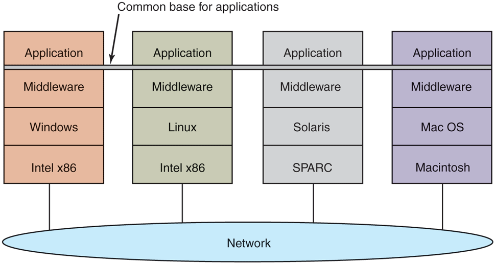
Positioning of middleware in a distributed system.
In a sense, middleware is like the operating system of a distributed system. That is why it is being discussed in a book on operating systems. On the other hand, it is not really an operating system, so the discussion will not go into much detail. For a comprehensive, book-length treatment of distributed systems, see Distributed Systems (Van Steen and Tanenbaum, 2017). In the remainder of this chapter, we will look quickly at the hardware used in a distributed system (i.e., the underlying computer network), then its communication software (the network protocols). After that we will consider a variety of paradigms used in these systems.
8.3.1 Network Hardware
Distributed systems are built on top of computer networks, so a brief introduction to the subject is in order. Networks come in two major varieties, LANs (Local Area Networks), which cover a building or a campus, and WANs (Wide Area Networks), which can be citywide, countrywide, or worldwide. The most important kind of LAN is Ethernet, so we will examine that as an example LAN. As our example WAN, we will look at the Internet, even though technically the Internet is not one network, but a federation of thousands of separate networks. However, for our purposes, it is sufficient to think of it as one WAN.
Ethernet
Classic Ethernet, which is described in IEEE Standard 802.3, consists of a coaxial cable to which a number of computers are attached. The cable is called the Ethernet, in reference to the luminiferous ether through which electromagnetic radiation was once thought to propagate. (When the nineteenth-century British physicist James Clerk Maxwell discovered that electromagnetic radiation could be described by a wave equation, scientists assumed that space must be filled with some ethereal medium in which the radiation was propagating. Only after the famous Michelson-Morley experiment in 1887, which failed to detect the ether, did physicists realize that radiation could propagate in a vacuum.)
In the very first version of Ethernet, a computer was attached to the cable by literally drilling a hole halfway through the cable and screwing in a wire leading to the computer. This was called a vampire tap, and is illustrated symbolically in Fig. 8-28(a). The taps were hard to get right, so before long, proper connectors were used. Nevertheless, electrically, all the computers were connected as if the cables on their network interface cards were soldered together.
Figure 8-28
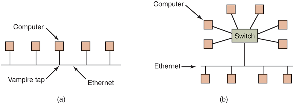
(a) Classic Ethernet. (b) Switched Ethernet.
With many computers hooked up to the same cable, a protocol is needed to prevent chaos. To send a packet on an Ethernet, a computer first listens to the cable to see if any other computer is currently transmitting. If not, it just begins transmitting a packet, which consists of a short header followed by a payload of 0 to 1500 bytes. If the cable is in use, the computer simply waits until the current transmission finishes, then it begins sending.
If two computers start transmitting simultaneously, a collision results, which both of them detect. Both respond by terminating their transmissions, waiting a random amount of time between 0 and and then starting again. If another collision occurs, all colliding computers randomize the wait into the interval 0 to and then try again. On each further collision, the maximum wait interval is doubled, reducing the chance of more collisions. This algorithm is known as binary exponential backoff. We saw it earlier to reduce polling overhead on locks.
An Ethernet has a maximum cable length and also a maximum number of computers that can be connected to it. To exceed either of these limits, a large building or campus can be wired with multiple Ethernets, which are then connected by devices called bridges. A bridge is a device that allows traffic to pass from one Ethernet to another when the source is on one side and the destination is on the other.
To avoid the problem of collisions, modern Ethernets use switches, as shown in Fig. 8-28(b). Each switch has some number of ports, to which can be attached a computer, an Ethernet, or another switch. When a packet successfully avoids all collisions and makes it to the switch, it is buffered there and sent out on the port where the destination machine lives. By giving each computer its own port, all collisions can be eliminated, at the cost of bigger switches. Compromises, with just a few computers per port, are also possible. In Fig. 8-28(b), a classical Ethernet with multiple computers connected to a cable by vampire taps is attached to one of the ports of the switch.
The Internet
The Internet evolved from the ARPANET, an experimental packet-switched network funded by the U.S. Dept. of Defense Advanced Research Projects Agency. It went live in December 1969 with three computers in California and one in Utah. It was designed at the height of the Cold War to a be a highly fault-tolerant network that would continue to relay military traffic even in the event of direct nuclear hits on multiple parts of the network by automatically rerouting traffic around the dead machines.
The ARPANET grew rapidly in the 1970s, eventually encompassing hundreds of computers. Then a packet radio network, a satellite network, and eventually thousands of Ethernets were attached to it, leading to the federation of networks we now know as the Internet.
The Internet consists of two kinds of computers, hosts and routers. Hosts are PCs, notebooks, smartphones, tablets, smart watches, servers, mainframes, and other computers owned by individuals or companies that want to connect to the Internet. Routers are specialized switching computers that accept incoming packets on one of many incoming lines and send them on their way along one of many outgoing lines. A router is similar to the switch of Fig. 8-28(b), but also differs from it in ways that will not concern us here. Routers are connected together in large networks, with each router having wires or fibers to many other routers and hosts. Large national or worldwide router networks are operated by telephone companies and ISPs (Internet Service Providers) for their customers.
Figure 8-29 shows a portion of the Internet. At the top we have one of the backbones, normally operated by a backbone operator. It consists of a number of routers connected by high-bandwidth fiber optics, with connections to backbones operated by other (competing) telephone companies. Usually, no hosts connect directly to the backbone, other than maintenance and test machines run by the telephone company.
Figure 8-29
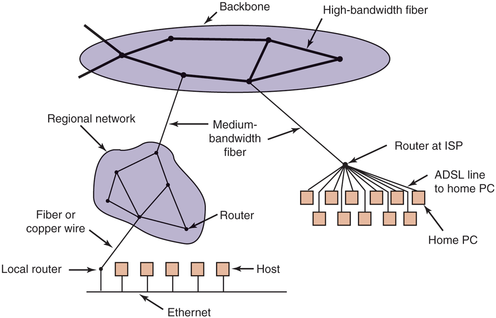
A portion of the Internet.
Attached to the backbone routers by medium-speed fiber optic connections are regional networks and routers at ISPs. In turn, corporate Ethernets each have a router on them and these are connected to regional network routers. Routers at ISPs are connected to modem banks used by the ISP’s customers. In this way, every host on the Internet has at least one path, and often many paths, to every other host.
All traffic on the Internet is sent in the form of packets. Each packet carries its destination address inside it, and this address is used for routing. When a packet comes into a router, the router extracts the destination address and looks (part of) it up in a table to find which outgoing line to send the packet on and thus to which router. This procedure is repeated until the packet reaches the destination host. The routing tables are highly dynamic and are updated continuously as routers and links go down and come back up and as traffic conditions change. The routing algorithms have been intensively studied and modified over the years. No doubt they will continue to be studied and modified in the years ahead as well.
8.3.2 Network Services and Protocols
All computer networks provide certain services to their users (hosts and processes), which they implement using certain rules about legal message exchanges. Below we will give a brief introduction to these topics.
Network Services
Computer networks provide services to the hosts and processes using them. Connection-oriented service is modeled after the telephone system. To talk to someone, you pick up the phone, dial the number, talk, and then hang up. Similarly, to use a connection-oriented network service, the service user first establishes a connection, uses the connection, and then releases the connection. The essential aspect of a connection is that it acts like a tube: the sender pushes objects (bits) in at one end, and the receiver takes them out in the same order at the other end.
In contrast, connectionless service is modeled after the postal system. Each message (letter) carries the full destination address, and each one is routed through the system independent of all the others. Normally, when two messages are sent to the same destination, the first one sent will be the first one to arrive. However, it is possible that the first one sent can be delayed so that the second one arrives first. With a connection-oriented service this is impossible.
Each service can be characterized by a quality of service. Some services are reliable in the sense that they never lose data. Usually, a reliable service is implemented by having the receiver confirm the receipt of each message by sending back a special acknowledgement packet so the sender is sure that it arrived. The acknowledgement process introduces overhead and delays, which are necessary to detect packet loss, but which do slow things down.
A typical situation in which a reliable connection-oriented service is appropriate is file transfer. The owner of the file wants to be sure that all the bits arrive correctly and in the same order they were sent. Very few file-transfer customers would prefer a service that occasionally scrambles or loses a few bits, even if it is much faster.
Reliable connection-oriented service has two relatively minor variants: message sequences and byte streams. In the former, the message boundaries are preserved. When two 1-KB messages are sent, they arrive as two distinct 1-KB messages, never as one 2-KB message. In the latter, the connection is simply a stream of bytes, with no message boundaries. When 2K bytes arrive at the receiver, there is no way to tell if they were sent as one 2-KB message, two 1-KB messages, 2048 1-byte messages, or something else. If the pages of a book are sent over a network to an imagesetter as separate messages, it might be important to preserve the message boundaries. On the other hand, with a terminal logging into a remote server system, a byte stream from the terminal to the computer is all that is needed. There are no message boundaries here.
For some applications, the delays introduced by acknowledgements are unacceptable. One such application is digitized voice traffic. It is preferable for telephone users to hear a bit of noise on the line or a garbled word from time to time than to introduce a delay to wait for acknowledgements.
Not all applications require connections. For example, to test the network, all that is needed is a way to send a single packet that has a high probability of arrival, but no guarantee. Unreliable (meaning not acknowledged) connectionless service is often called datagram service, in analogy with telegram service, which also does not provide an acknowledgement back to the sender.
In other situations, the convenience of not having to establish a connection to send one short message is desired, but reliability is essential. The acknowledged datagram service can be provided for these applications. It is like sending a registered letter and requesting a return receipt. When the receipt comes back, the sender is absolutely sure that the letter was delivered to the intended party and not lost along the way.
Still another service is the request-reply service. In this service, the sender transmits a single datagram containing a request; the reply contains the answer. For example, a query to the local library asking where Uighur is spoken falls into this category. Request-reply is commonly used to implement communication in the client-server model: the client issues a request and the server responds to it. Figure 8-30 summarizes the types of services we have discussed.
Figure 8-30
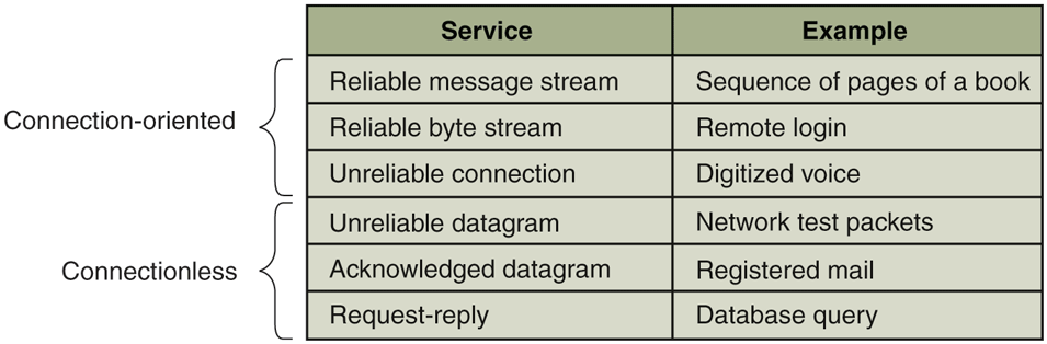
Six different types of network service.
Network Protocols
All networks have highly specialized rules for what messages may be sent and what responses may be returned in response to these messages. For example, under certain circumstances (e.g., file transfer), when a message is sent from a source to a destination, the destination is required to send an acknowledgement back indicating correct receipt of the message. Under other circumstances (e.g., digital telephony), no such acknowledgement is expected. The set of rules by which particular computers communicate is called a protocol. Many protocols exist, including router-router protocols, host-host protocols, and others. For a thorough treatment of computer networks and their protocols, see Computer Networks, 6/e (Tanenbaum et al., 2020).
All modern networks use what is called a protocol stack to layer different protocols on top of one another. At each layer, different issues are dealt with. For example, at the bottom level protocols define how to tell where in the bit stream a packet begins and ends. At a higher level, protocols deal with how to route packets through complex networks from source to destination. And at a still higher level, they make sure that all the packets in a multipacket message have arrived correctly and in the proper order.
Since most distributed systems use the Internet as a base, the key protocols these systems use are the two major Internet protocols: IP and TCP. IP (Internet Protocol) is a datagram protocol in which a sender injects a datagram of up to 64 KB into the network and hopes that it arrives. No guarantees are given. The datagram may be fragmented into smaller packets as it passes through the Internet. These packets travel independently, possibly along different routes. When all the pieces get to the destination, they are assembled in the correct order and delivered.
Two versions of IP are currently in use, v4 and v6. At the moment, v4 still dominates, so we will describe that here, but v6 is up and coming. Each v4 packet starts with a 40-byte header that contains a 32-bit source address and a 32-bit destination address among other fields. These are called IP addresses and form the basis of Internet routing. They are conventionally written as four decimal numbers in the range 0–255 separated by dots, as in 192.31.231.65. When a packet arrives at a router, the router extracts the IP destination address and uses that for routing.
Since IP datagrams are not acknowledged, IP alone is not sufficient for reliable communication in the Internet. To provide reliable communication, another protocol, TCP (Transmission Control Protocol), is usually layered on top of IP. TCP uses IP to provide connection-oriented streams. To use TCP, a process first establishes a connection to a remote process. The process required is specified by the IP address of a machine and a port number on that machine, to which processes interested in receiving incoming connections listen. Once that has been done, it just pumps bytes into the connection and they are guaranteed to come out the other end undamaged and in the correct order. The TCP implementation achieves this guarantee by using sequence numbers, checksums, and retransmissions of incorrectly received packets. All of this is transparent to the sending and receiving processes. They just see reliable interprocess communication, just like a UNIX pipe.
To see how all these protocols interact, consider the simplest case of a very small message that does not need to be fragmented at any level. The host is on an Ethernet connected to the Internet. What happens exactly? The user process generates the message and makes a system call to send it on a previously established TCP connection. The kernel protocol stack adds a TCP header and then an IP header to the front. of the message. Then it goes to the Ethernet driver, which adds an Ethernet header directing the packet to the router on the Ethernet. This router then injects the packet into the Internet, as depicted in Fig. 8-31.
Figure 8-31
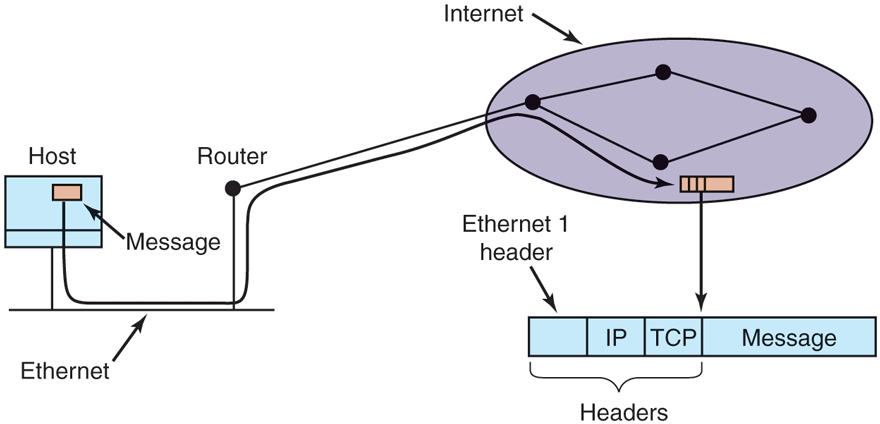
Accumulation of packet headers.
To establish a connection with a remote host (or even to send it a datagram), it is necessary to know its IP address. Since managing lists of 32-bit IP addresses is inconvenient for people, a scheme called DNS (Domain Name System) was invented as a database that maps ASCII names for hosts onto their IP addresses. Thus it is possible to use the DNS name star.cs.vu.nl instead of the corresponding IP address 130.37.24.6. DNS names are commonly known because Internet email addresses are of the form user-name@DNS-host-name. This naming system allows the mail program on the sending host to look up the destination host’s IP address in the DNS database, establish a TCP connection to the mail daemon process there, and send the message as a file. The user-name is sent along to identify which mailbox to put the message in.
8.3.3 Document-Based Middleware
Now that we have some background on networks and protocols, we can start looking at different middleware layers that can overlay the basic network to produce a consistent paradigm for applications and users. We will start with a simple but well-known example: the World Wide Web. The Web was invented by Tim Berners-Lee at CERN, the European Nuclear Physics Research Center, in 1989 and since then has spread like wildfire all over the world.
The original paradigm behind the Web was quite simple: every computer can hold one or more documents, called Web pages. Each Web page contains text, images, icons, sounds, movies, and the like, as well as hyperlinks (pointers) to other Web pages. When a user requests a Web page using a program called a Web browser, the page is displayed on the screen. Clicking on a link causes the current page to be replaced on the screen by the page pointed to. Although many bells and whistles have recently been grafted onto the Web, the underlying paradigm is still clearly present: the Web is a great big directed graph of documents that can point to other documents, as shown in Fig. 8-32.
Figure 8-32
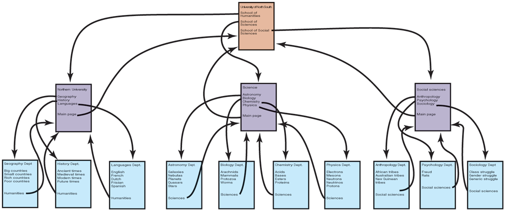
The Web is a big directed graph of documents.
Each Web page has a unique address, called a URL (Uniform Resource Locator), of the form protocol://DNS-name/file-name. The protocol is most commonly http (HyperText Transfer Protocol), and its secure cousin https, but ftp and others also exist. Then comes the DNS name of the host containing the file. Finally, there is a local file name telling which file is needed. Thus, a URL uniquely specifies a single file worldwide
The way the whole system hangs together is as follows. The Web is fundamentally a client-server system, with the user being the client and the Website being the server. When the user provides the browser with a URL, either by typing it in or clicking on a hyperlink on the current page, the browser takes certain steps to fetch the requested Web page. As a simple example, suppose the URL provided is http://www.minix3.org/getting-started/index.html. The browser then takes the following steps to get the page.
The browser asks DNS for the IP address of www.minix3.org.
DNS replies with 66.147.238.215.
The browser makes a TCP connection to port 80 on 66.147.238.215.
It then sends a request asking for the file getting-started/index.html.
The www.minix3.org server sends the file getting-started/index.html.
The browser displays all the text in getting-started/index.html.
Meanwhile, the browser fetches and displays all images on the page.
The TCP connection is released.
To a first approximation, this is the basis of the Web and how it works. Many other features have since been added to the basic Web, including style sheets, dynamic Web pages that are generated on the fly, Web pages that contain small programs or scripts that execute on the client machine, and more, but they are outside the scope of this discussion.
8.3.4 File-System-Based Middleware
The basic idea behind the Web is to make a distributed system look like a giant collection of hyperlinked documents. A second approach is to make a distributed system look like a great big file system. In this section, we will look at some of the issues involved in designing a worldwide file system.
Using a file-system model for a distributed system means that there is a single global file system, with users all over the world able to read and write files for which they have authorization. Communication is achieved by having one process write data into a file and having other ones read them back. Many of the standard file-system issues arise here, but also some new ones related to distribution.
Transfer Model
The first issue is the choice between the upload/download model and the remote-access model. In the former, shown in Fig. 8-33(a), a process accesses a file by first copying it from the remote server where it lives. If the file is only to be read, the file is then read locally, for high performance. If the file is to be written, it is written locally. When the process is done with it, the updated file is put back on the server. With the remote-access model, the file stays on the server and the client sends commands there to get work done there, as shown in Fig. 8-33(b).
Figure 8-33
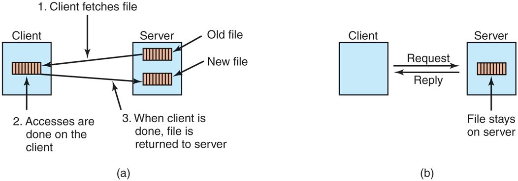
(a) The upload/download model. (b) The remote-access model.
The advantages of the upload/download model are its simplicity, and the fact that transferring entire files at once is more efficient than transferring them in small pieces. The disadvantages are that there must be enough storage for the entire file locally, moving the entire file is wasteful if only parts of it are needed, and consistency problems arise if there are multiple concurrent users.
The Directory Hierarchy
Files are only part of the story. The other part is the directory system. All distributed file systems support directories containing multiple files. The next design issue is whether all clients have the same view of the directory hierarchy. As an example of what we mean, consider Fig. 8-34. In Fig. 8-34(a), we show two file servers, each holding three directories and some files. In Fig. 8-34(b), we have a system in which all clients (and other machines) have the same view of the distributed file system. If the path /D/E/x is valid on one machine, it is valid on all of them.
Figure 8-34
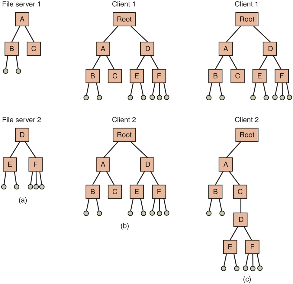
(a) Two file servers. The squares are directories and the circles are files. (b) A system in which all clients have the same view of the file system. (c) A system in which different clients have different views of the file system.
In contrast, in Fig. 8-34(c), different machines can have different views of the file system. To repeat the preceding example, the path /D/E/x might well be valid on client 1 but not on client 2. In systems that manage multiple file servers by remote mounting, Fig. 8-34(c) is the norm. It is flexible and straightforward to implement, but it has the disadvantage of not making the entire system behave like a single old-fashioned timesharing system. In a timesharing system, the file system looks the same to any process, as in the model of Fig. 8-34(b). This property makes a system easier to program and understand.
A closely related question is whether or not there is a global root directory, which all machines recognize as the root. One way to have a global root directory is to have the root contain one entry for each server and nothing else. Under these circumstances, paths take the form /server/path, which has its own disadvantages, but at least is the same everywhere in the system.
Naming Transparency
The principal problem with this form of naming is that it is not fully transparent. Two forms of transparency are relevant in this context and are worth distinguishing. The first one, location transparency, means that the path name gives no hint as to where the file is located. A path like /server1/dir1/dir2/x tells everyone that x is located on server 1, but it does not tell where that server is located. The server is free to move anywhere it wants to in the network without the path name having to be changed. Thus this system has location transparency.
However, suppose that file x is extremely large and space is tight on server 1. Furthermore, suppose that there is plenty of room on server 2. The system might well like to move x to server 2 automatically. Unfortunately, when the first component of all path names is the server, the system cannot move the file to the other server automatically, even if dir1 and dir2 exist on both servers. The problem is that moving the file automatically changes its path name from /server1/dir1/dir2/x to /server2/dir1/dir2/x. Programs that have the former string built into them will cease to work if the path changes. A system in which files can be moved without their names changing is said to have location independence. A distributed system that embeds machine or server names in path names clearly is not location independent. One based on remote mounting is not, either, since it is not possible to move a file from one file group (the unit of mounting) to another and still be able to use the old path name. Location independence is not easy to achieve, but it is a desirable property to have in a distributed system.
To summarize what we said earlier, there are three common approaches to file and directory naming in a distributed system:
such as /machine/path or machine:path.
Mounting remote file systems onto the local file hierarchy.
A single name space that looks the same on all machines.
The first two are easy to implement, especially as a way to connect existing systems that were not designed for distributed use. The latter is difficult and requires careful design, but makes life easier for programmers and users.
Semantics of File Sharing
When two or more users share the same file, it is necessary to define the semantics of reading and writing precisely to avoid problems. In single-processor systems, the semantics normally state that when a read system call follows a write system call, the read returns the value just written, as shown in Fig. 8-35(a). Similarly, when two writes happen in quick succession, followed by a read, the value read is the value stored by the last write. In effect, the system enforces a total ordering on all system calls, and all processors see the same ordering. We will refer to this model as sequential consistency.
Figure 8-35
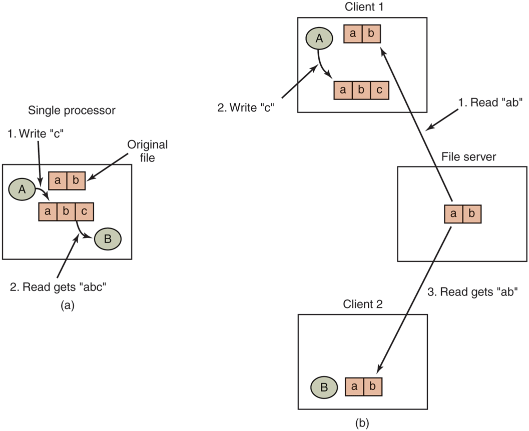
(a) Sequential consistency. (b) In a distributed system with caching, reading a file may return an obsolete value.
In a distributed system, sequential consistency can be achieved easily as long as there is only one file server and clients do not cache files. All reads and writes go directly to the file server, which processes them strictly sequentially.
In practice, however, the performance of a distributed system in which all file requests must go to a single server is frequently poor. This problem is often solved by allowing clients to maintain local copies of heavily used files in their private caches. However, if client 1 modifies a cached file locally and shortly thereafter client 2 reads the file from the server, the second client will get an obsolete file, as illustrated in Fig. 8-35(b).
One way out of this difficulty is to propagate all changes to cached files back to the server immediately. Although conceptually simple, this approach is inefficient. An alternative solution is to relax the semantics of file sharing. Instead of requiring a read to see the effects of all previous writes, one can have a new rule that says: ‘‘Changes to an open file are initially visible only to the process that made them. Only when the file is closed are the changes visible to other processes.’’ The adoption of such a rule does not change what happens in Fig. 8-35(b), but it does redefine the actual behavior (B getting the original value of the file) as being the correct one. When client 1 closes the file, it sends a copy back to the server, so that subsequent reads get the new value, as required. Effectively, this is the upload/download model shown in Fig. 8-33. This semantic rule is widely implemented and is known as session semantics.
Using session semantics raises the question of what happens if two or more clients are simultaneously caching and modifying the same file. One solution is to say that as each file is closed in turn, its value is sent back to the server, so the final result depends on who closes last. A less pleasant, but slightly easier to implement, alternative is to say that the final result is one of the candidates, but leave the choice of which one unspecified.
An alternative approach to session semantics is to use the upload/download model, but to automatically lock a file that has been downloaded. Attempts by other clients to download the file will be held up until the first client has returned it. If there is a heavy demand for a file, the server could send messages to the client holding the file, asking it to hurry up, but that may or may not help. All in all, getting the semantics of shared files right is a tricky business with no elegant and efficient solutions.
8.3.5 Object-Based Middleware
Now let us take a look at a third paradigm. Instead of saying that everything is a document or everything is a file, we say that everything is an object. An object in this context is a collection of variables that are bundled together with a set of access procedures, called methods. Processes are not permitted to access the variables directly. Instead, they are required to invoke the methods.
Some programming languages, such as C++ and Java, are object oriented, but these are language-level objects rather than run-time objects. One well-known system based on run-time objects is CORBA (Common Object Request Broker Architecture) (Vinoski, 1997), which first saw light of day in 1991 and was actively updated until as late as 2012. CORBA is a client-server system, in which client processes on client machines can invoke operations on objects located on (possibly remote) server machines. CORBA was designed for a heterogeneous system running a variety of hardware platforms and operating systems and programmed in a variety of languages. To make it possible for a client on one platform to invoke a server on a different platform, ORBs (Object Request Brokers) are interposed between client and server to allow them to match up. The ORBs play an important role in CORBA, even providing the system with its name.
Each CORBA object is defined by an interface definition in a language called IDL (Interface Definition Language), which tells what methods the object exports and what parameter types each one expects. The IDL specification can be compiled into a client stub procedure and stored in a library. If a client process knows in advance that it will need to access a certain object, it is linked with the object’s client stub code. The IDL specification can also be compiled into a skeleton procedure that is used on the server side. If it is not known in advance which CORBA objects a process needs to use, dynamic invocation is also possible, but how that works is beyond the scope of our treatment.
The function of the ORBs is to hide all the low-level distribution and communication details from the client and server code. In particular, the ORBs hide from the client the location of the server, whether the server is a binary program or a script, what hardware and operating system the server runs on, whether the object is currently active, and how the two ORBs communicate (e.g., using TCP/IP, RPC, or shared memory).
A serious problem with CORBA is that every object is located on only one server, which means the performance will be terrible for objects that are heavily used on client machines around the world. In practice, CORBA functions acceptably only in small-scale systems, such as to connect processes on one computer, one LAN, or within a single company.
8.3.6 Coordination-Based Middleware
Our last paradigm for a distributed system is called coordination-based middleware. We will discuss it by looking at the Linda system, an academic research project that started the whole field.
Linda started as a novel system for communication and synchronization developed at Yale University by David Gelernter and his student Nick Carriero (Carriero and Gelernter, 1986; Carriero and Gelernter, 1989; and Gelernter, 1985). In Linda, independent processes communicate via an abstract tuple space. The tuple space is global to the entire system, and processes on any machine can insert tuples into the tuple space or remove tuples from the tuple space without regard to how or where they are stored. To the user, the tuple space looks like a big, global shared memory, as we have seen in various forms before, as in Fig. 8-21(c).
A tuple is like a structure in C or Java. It consists of one or more fields, each of which is a value of some type supported by the base language (Linda is implemented by adding a library to an existing language, such as C). For C-Linda, field types include integers, long integers, and floating-point numbers, as well as composite types such as arrays (including strings) and structures (but not other tuples). Unlike objects, tuples are pure data; they do not have any associated methods. Figure 8-36 shows three tuples as examples.
Figure 8-36
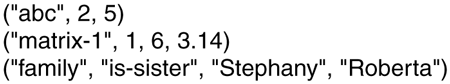
Three Linda tuples.
Four operations are provided on tuples. The first one, out, puts a tuple into the tuple space. For example,
out("abc", 2, 5);
puts the tuple ("abc", 2, 5) into the tuple space. The fields of out are normally constants, variables, or expressions, as in
out("matrix-1", i, j, 3.14);
which outputs a tuple with four fields, the second and third of which are determined by the current values of the variables i and j.
Tuples are retrieved from the tuple space by the in primitive. They are addressed by content rather than by name or address. The fields of in can be expressions or formal parameters. Consider, for example,
in("abc", 2, ?i);
This operation ‘‘searches’’ the tuple space for a tuple consisting of the string ‘‘abc’’, the integer 2, and a third field containing any integer (assuming that i is an integer). If found, the tuple is removed from the tuple space and the variable i is assigned the value of the third field. The matching and removal are atomic, so if two processes execute the same in operation simultaneously, only one of them will succeed, unless two or more matching tuples are present. The tuple space may even contain multiple copies of the same tuple.
The matching algorithm used by in is straightforward. The fields of the in primitive, called the template, are (conceptually) compared to the corresponding fields of every tuple in the tuple space. A match occurs if the following three conditions are all met:
The template and the tuple have the same number of fields.
The types of the corresponding fields are equal.
Each constant or variable in the template matches its tuple field.
Formal parameters, indicated by a question mark followed by a variable name or type, do not participate in the matching (except for type checking), although those containing a variable name are assigned after a successful match.
If no matching tuple is present, the calling process is suspended until another process inserts the needed tuple, at which time the called is automatically revived and given the new tuple. The fact that processes block and unblock automatically means that if one process is about to output a tuple and another is about to input it, it does not matter which goes first. The only difference is that if the in is done before the out, there will be a slight delay until the tuple is available for removal.
The fact that processes block when a needed tuple is not present can be put to many uses. For example, it can be used to implement semaphores. To create or do an up on semaphore S, a process can execute
out("semaphore S");
To do a down, it does
in("semaphore S");
The state of semaphore S is determined by the number of (‘‘semaphore S’’) tuples in the tuple space. If none exist, any attempt to get one will block until some other process supplies one.
In addition to out and in, Linda also has a primitive operation read, which is the same as in except that it does not remove the tuple from the tuple space. There is also a primitive eval, which causes its parameters to be evaluated in parallel and the resulting tuple to be put in the tuple space. This mechanism can be used to perform an arbitrary computation. This is how parallel processes are created in Linda.
Publish/Subscribe
Our next example of a coordination-based model was inspired by Linda and is called publish/subscribe (Oki et al., 1993). It consists of a number of processes connected by a broadcast network. Each process can be a producer of information, a consumer of information, or both.
When an information producer has a new piece of information (e.g., a new stock price), it broadcasts the information as a tuple on the network. This action is called publishing. Each tuple contains a hierarchical subject line containing multiple fields separated by periods. Processes that are interested in certain information can subscribe to certain subjects, including the use of wildcards in the subject line. Subscription is done by telling a tuple daemon process on the same machine that monitors published tuples what subjects to look for.
Publish/subscribe is implemented as illustrated in Fig. 8-37. When a process has a tuple to publish, it broadcasts it out onto the local LAN. The tuple daemon on each machine copies all broadcasted tuples into its RAM. It then inspects the subject line to see which processes are interested in it, forwarding a copy to each one that is. Tuples can also be broadcast over a wide area network or the Internet by having one machine on each LAN act as an information router, collecting all published tuples and then forwarding them to other LANs for rebroadcasting. This forwarding can also be done intelligently, forwarding a tuple to a remote LAN only if that remote LAN has at least one subscriber who wants the tuple. Doing this requires having the information routers exchange information about subscribers.
Figure 8-37
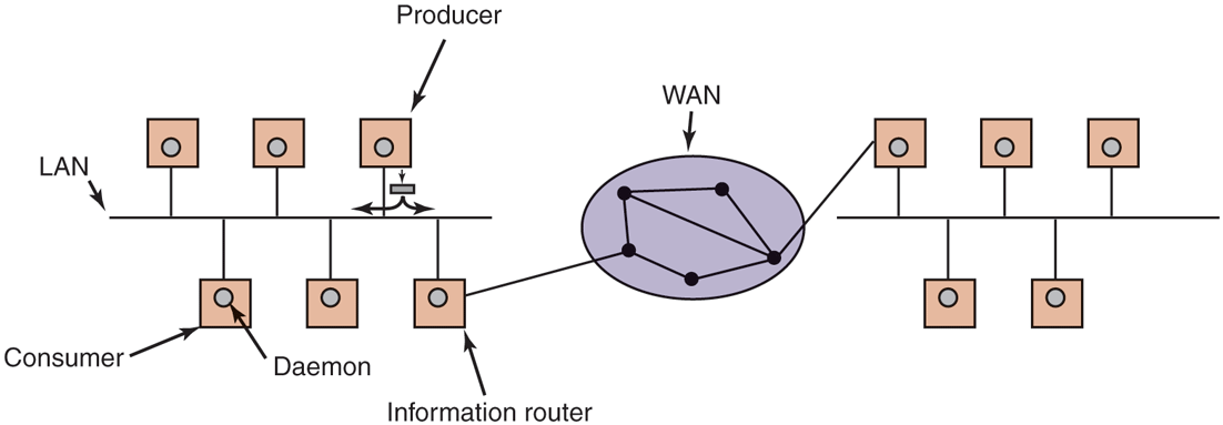
The publish/subscribe architecture.
Various kinds of semantics can be implemented, including reliable delivery and guaranteed delivery, even in the presence of crashes. In the latter case, it is necessary to store old tuples in case they are needed later. One way to store them is to hook up a database system to the system and have it subscribe to all tuples. This can be done by wrapping the database system in an adapter, to allow an existing database to work with the publish/subscribe model. As tuples come by, the adapter captures all of them and puts them in the database.
The publish/subscribe model fully decouples producers from consumers, as does Linda. However, sometimes it is useful to know who else is out there. This information can be acquired by publishing a tuple that basically asks: ‘‘Who out there is interested in x?’’ Responses come back in the form of tuples that say: ‘‘I am interested in x.’’