8.2 Multicomputers
Multiprocessors are popular and attractive because they offer a simple communication model: all CPUs share a common memory. Processes can write messages to memory that can then be read by other processes. Synchronization can be done using mutexes, semaphores, monitors, and other well-established techniques. The only fly in the ointment is that large multiprocessors are difficult to build and thus expensive. And very large ones are impossible to build at any price. So something else is needed if we are to scale up to large numbers of CPUs.
To get around these problems, much research has been done on multicomputers, which are tightly coupled CPUs that do not share memory. Each one has its own memory, as shown in Fig. 8-1(b). These systems are also known by a variety of other names, including cluster computers and COWs (Clusters Of Workstations). Cloud computing services are always built on multicomputers because they need to be large.
Multicomputers are easy to build because the basic component is just a stripped-down PC, without a keyboard, mouse, or monitor, but with a high-performance network interface card. Of course, the secret to getting high performance is to design the interconnection network and the interface card cleverly. This problem is completely analogous to building the shared memory in a multiprocessor [e.g., see Fig. 8-1(b)]. However, the goal is to send messages on a microsecond time scale, rather than access memory on a nanosecond time scale, so it is simpler, cheaper, and easier to accomplish.
In the following sections, we will first take a brief look at multicomputer hardware, especially the interconnection hardware. Then we will move onto the software, starting with low-level communication software, then high-level communication software. We will also look at a way shared memory can be achieved on systems that do not have it. Finally, we will examine scheduling and load balancing.
8.2.1 Multicomputer Hardware
The basic node of a multicomputer consists of a CPU, memory, a network interface, and sometimes a hard disk. The node may be packaged in a standard PC case, but the monitor, keyboard, and mouse are nearly always absent. Sometimes this configuration is called a headless workstation because there is no user with a head in front of it. A workstation with a human user should logically be called a ‘‘headed workstation,’’ but for some reason it is not. In some cases, the PC contains a two-way or four-way multiprocessor board, possibly each with a dual-, quad- or octa-core chip, instead of a single CPU, but for simplicity, we will assume that each node has one CPU. Often hundreds or even thousands of nodes are hooked together to form a multicomputer. Below we will say a little about how this hardware is organized.
Interconnection Technology
Each node has a network interface card with one or two cables (or fibers) coming out of it. These cables connect either to other nodes or to switches. In a small system, there may be one switch to which all the nodes are connected in the star topology of Fig. 8-16(a). Modern switched Ethernets use this topology within an office or a small building.
Figure 8-16
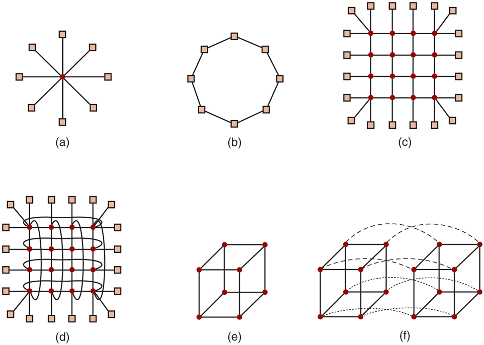
Various interconnect topologies. (a) A single switch. (b) A ring. (c) A grid. (d) A double torus. (e) A cube. (f) A 4D hypercube.
As an alternative to the single-switch design, the nodes may form a ring, with two wires coming out the network interface card, one into the node on the left and one going into the node on the right, as shown in Fig. 8-16(b). In this topology, no switches are needed and none are shown.
The grid or mesh of Fig. 8-16(c) is a two-dimensional design that has been used in many commercial systems. It is highly regular and easy to scale up to large sizes. It has a diameter, which is the longest path between any two nodes, and which increases only as the square root of the number of nodes. A variant on the grid is the double torus of Fig. 8-16(d), which is a grid with the edges connected. Not only is it more fault tolerant than the grid, but the diameter is also less because the opposite corners can now communicate in only two hops.
The cube of Fig. 8-16(e) is a regular three-dimensional topology. We have illustrated a but in the most general case it could be a In Fig. 8-16(f), we have a four-dimensional cube built from two three-dimensional cubes with the corresponding nodes connected. We could make a five-dimensional cube by cloning the structure of Fig. 8-16(f) and connecting the corresponding nodes to form a block of four cubes. To go to six dimensions, we could replicate the block of four cubes and interconnect the corresponding nodes, and so on. An n-dimensional cube formed this way is called a hypercube.
Many parallel computers use a hypercube topology because the diameter grows linearly with the dimensionality. Put in other words, the diameter is the base 2 logarithm of the number of nodes. For example, a 10-dimensional hypercube has 1024 nodes but a diameter of only 10, giving excellent delay properties. Note that in contrast, 1024 nodes arranged as a grid have a diameter of 62, more than six times worse than the hypercube. The price paid for the smaller diameter is that the fanout, and thus the number of links (and the cost), is much larger for the hypercube.
Two kinds of switching schemes are used in multicomputers. In the first one, each message is first broken up (either by the user software or the network interface) into a chunk of some maximum length called a packet. The switching scheme, called store-and-forward packet switching, consists of the packet being injected into the first switch by the source node’s network interface board, as shown in Fig. 8-17(a). The bits come in one at a time, and when the whole packet has arrived at an input buffer, it is copied to the line leading to the next switch along the path, as shown in Fig. 8-17(b). When the packet arrives at the switch attached to the destination node, as shown in Fig. 8-17(c), the packet is copied to that node’s network interface board and eventually to its RAM.
Figure 8-17
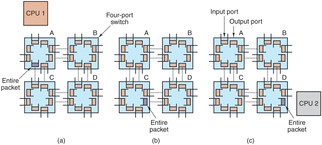
Store-and-forward packet switching.
While store-and-forward packet switching is flexible and efficient, it does have the problem of increasing latency (delay) through the interconnection network. Suppose that the time to move a packet one hop in Fig. 8-17 is T nsec. Since the packet must be copied four times to get it from CPU 1 to CPU 2 (to A, to C, to D, and to the destination CPU), and no copy can begin until the previous one is finished, the latency through the interconnection network is 4T . One way out is to design a network in which a packet can be logically divided into smaller units. As soon as the first unit arrives at a switch, it can be forwarded, even before the tail has arrived. Conceivably, the unit could be as small as 1 bit.
The other switching regime, circuit switching, consists of the first switch first establishing a path through all the switches to the destination switch. Once that path has been set up, the bits are pumped all the way from the source to the destination nonstop as fast as possible. There is no intermediate buffering at the intervening switches. Circuit switching requires a setup phase, which takes some time, but is faster once the setup has been completed. After the packet has been sent, the path must be torn down again. A variation on circuit switching, called wormhole routing, breaks each packet up into subpackets and allows the first subpacket to start flowing even before the full path has been built.
Network Interfaces
All the nodes in a multicomputer have either a plug-in board containing the node’s connection to the interconnection network that holds the multicomputer together or a network chip on the mother board that does the same thing. The way these boards (and chips) are built and how they connect to the main CPU and RAM have substantial implications for the operating system. We will now briefly look at some of the issues here.
In virtually all multicomputers, the interface board contains substantial RAM for holding outgoing and incoming packets. Usually, an outgoing packet has to be copied to the interface board’s RAM before it can be transmitted to the first switch. The reason for this design is that many interconnection networks are synchronous, so that once a packet transmission has started, the bits must continue flowing at a constant rate. If the packet is in the main RAM, this continuous flow out onto the network cannot be guaranteed due to other traffic on the memory bus. Using a dedicated RAM on the interface board eliminates this problem. This design is shown in Fig. 8-18.
Figure 8-18
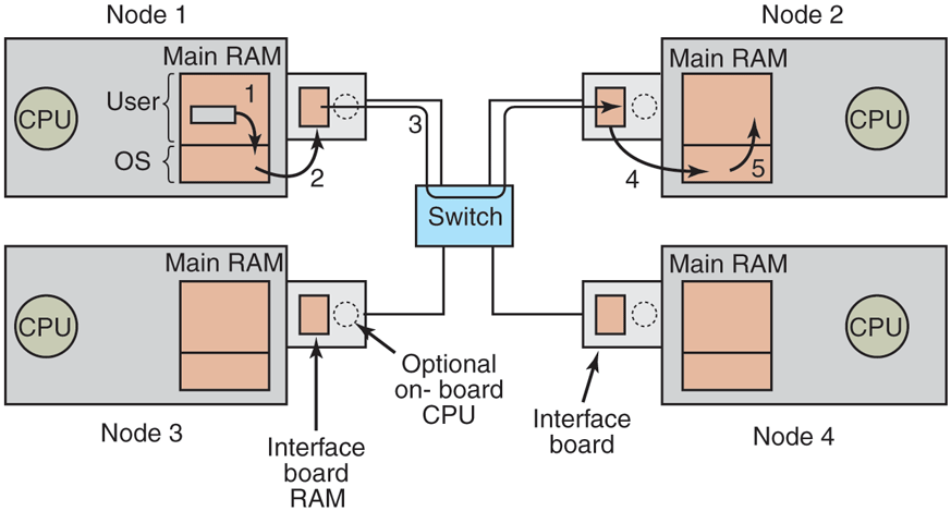
Position of the network interface boards in a multicomputer.
The same problem occurs with incoming packets. The bits arrive from the network at a constant and often extremely high rate. If the network interface board cannot store them in real time as they arrive, data will be lost. Again here, trying to go over the system bus (e.g., the PCI bus) to the main RAM is too risky. Since the network board is typically plugged into the PCI bus, this is the only connection it has to the main RAM, so competing for this bus with the disk and every other I/O device is inevitable. It is safer to store incoming packets in the interface board’s private RAM and then copy them to the main RAM later.
The interface board may have one or more DMA channels or even a complete CPU (or maybe even multiple CPUs) on board. The DMA channels can copy packets between the interface board and the main RAM at high speed by requesting block transfers on the system bus, thus transferring several words without having to request the bus separately for each word. However, it is precisely this kind of block transfer, which ties up the system bus for multiple bus cycles, that makes the interface board RAM necessary in the first place.
Many interface boards have a CPU and sometimes an FPGA on them, possibly in addition to one or more DMA channels. Such a network interface is called a smart NIC, and they are becoming increasingly powerful and are very common. This design means that the main CPU can offload some work to the network board, such as handling reliable transmission (if the underlying hardware can lose packets), multicasting (sending a packet to more than one destination), compression/decompression, encryption/decryption, and taking care of protection in a system that has multiple processes. However, having two CPUs means that they must synchronize to avoid race conditions, which adds extra overhead and means more work for the operating system.
Copying data across layers is safe, but not necessarily efficient. For instance, a browser requesting data from a remote web server will create a request in the browser’s address space. That request is subsequently copied to the kernel so that TCP and IP can handle it. Next, the data are copied to the memory of the network interface. On the other end, the inverse happens: the data are copied from the network card to a kernel buffer, and from a kernel buffer to the Web server. Quite a few copies, unfortunately. Each copy introduces overhead, not just the copying itself, but also the pressure on the cache, TLB, etc. As a consequence, the latency over such network connections is high.
In the next section, we discuss techniques to reduce the overhead due to copying, cache pollution, and context switching as much as possible.
8.2.2 Low-Level Communication Software
The enemy of high-performance communication in multicomputer systems is excess copying of packets. In the best case, there will be one copy from RAM to the interface board at the source node, one copy from the source interface board to the destination interface board (if no storing and forwarding along the path occurs), and one copy from there to the destination RAM, a total of three copies. However, in many systems it is even worse. In particular, if the interface board is mapped into kernel virtual address space and not user virtual address space, a user process can send a packet only by issuing a system call that traps to the kernel. The kernel may have to copy the packets to its own memory both on output and on input, for example, to avoid page faults while transmitting over the network. Also, the receiving kernel probably does not know where to put incoming packets until it has had a chance to examine them. These five copy steps are illustrated in Fig. 8-18.
If copies to and from RAM are the bottleneck, the extra copies to and from the kernel may double the end-to-end delay and cut the throughput in half. To avoid this performance hit, many multicomputers map the interface board directly into user space and allow the user process to put the packets on the board directly, without the kernel being involved. While this approach definitely helps performance, it introduces two problems.
First, what if several processes are running on the node and both need network access to send packets? Which one gets the interface board in its address space? Having a system call to map the board in and out of a virtual address space is expensive, but if only one process gets the board, how do the other ones send packets? And what happens if the board is mapped into process A’s virtual address space and a packet arrives for process B, especially if A and B have different owners, neither of whom wants to put in any effort to help the other?
One solution is to map the interface board into all processes that need it, but then a mechanism is needed to avoid race conditions. For example, if A claims a buffer on the interface board, and then, due to a time slice, B runs and claims the same buffer, disaster results. Some kind of synchronization mechanism is needed, but these mechanisms, such as mutexes, work only when the processes are assumed to be cooperating. In a shared environment with multiple users all in a hurry to get their work done, one user might just lock the mutex associated with the board and never release it. The conclusion here is that mapping the interface board into user space really works well only when there is just one user process running on each node unless special precautions are taken (e.g., different processes get different portions of the interface RAM mapped into their address spaces).
The second problem is that the kernel may well need access to the interconnection network itself, for example, to access the file system on a remote node. Having the kernel share the interface board with any users is not a good idea. Suppose that while the board was mapped into user space, a kernel packet arrived. Or suppose that the user process sent a packet to a remote machine pretending to be the kernel. The conclusion is that the simplest design is to have two network interface boards, one mapped into user space for application traffic and one mapped into kernel space for use by the operating system. Many multicomputers do precisely this.
On the other hand, newer network interfaces are frequently multiqueue, which means that they have more than one buffer to support multiple users efficiently. For instance, network cards can easily have 16 send and 16 receive queues, making them virtualizable to many virtual ports. Better still, the card often supports core affinity. Specifically, it has its own hashing logic to help steer each packet to a suitable process. As it is faster to process all segments in the same TCP flow on the same processor (where the caches are warm), the card can use the hashing logic to hash the TCP flow fields (IP addresses and TCP port numbers) and add all segments with the same hash on the same queue that is served by a specific core. This is also useful for virtualization, as it allows us to give each virtual machine its own queue.
Node-to-Network Interface Communication
Another issue is how to get packets onto the interface board. The fastest way is to use the DMA chip on the board to just copy them in from RAM. The problem with this approach is that DMA may use physical rather than virtual addresses and runs independently of the CPU, unless an I/O MMU is present. To start with, although a user process certainly knows the virtual address of any packet it wants to send, it generally does not know the physical address. Making a system call to do the virtual-to-physical mapping is undesirable, since the point of putting the interface board in user space in the first place was to avoid having to make a system call for each packet to be sent.
In addition, if the operating system decides to replace a page while the DMA chip is copying a packet from it, the wrong data will be transmitted. Worse yet, if the operating system replaces a page while the DMA chip is copying an incoming packet to it, not only will the incoming packet be lost, but also a page of innocent memory will be ruined, probably with disastrous consequences shortly.
These problems can be avoided by having system calls to pin and unpin pages in memory, marking them as temporarily unpageable. However, having to make a system call to pin the page containing each outgoing packet and then having to make another call later to unpin it is expensive. If packets are small, say, 64 bytes or less, the overhead for pinning and unpinning every buffer is prohibitive. For large packets, say, 1 KB or more, it may be tolerable. For sizes in between, it depends on the details of the hardware. Besides introducing a performance hit, pinning and unpinning pages add to the software complexity. And if user processes can pin pages, what is to prevent a greedy process from pinning all its page to keep them from being paged out in order to improve its performance?
Remote Direct Memory Access
In some fields, high network latencies are simply not acceptable. For instance, for certain applications in high-performance computing the computation time is strongly dependent on the network latency. Likewise, high-frequency trading is all about having computers perform transactions (buying and selling stock) at extremely high speeds—every microsecond counts. Whether or not it is wise to have computer programs trade millions of dollars worth of stock in a millisecond, when pretty much all software tends to be buggy, is an interesting question for dining philosophers to consider when they are not busy grabbing their forks. But not for this book. The point here is that if you manage to get the latency down, it is sure to make you very popular with your boss.
In these scenarios, it pays to reduce the amount of copying. For this reason, some network interfaces support RDMA (Remote Direct Memory Access), a technique that allows one machine to perform a direct memory access from one computer to that of another. The RDMA does not involve either of the operating system and the data is directly fetched from, or written to, application memory.
RDMA sounds great, but it is not without its disadvantages. Just like normal DMA, the operating system on the communicating nodes must pin the pages involved in the data exchange. Also, just placing data in a remote computer’s memory will not reduce the latency much if the other program is not aware of it. A successful RDMA does not automatically come with an explicit notification. Instead, a common solution is that a receiver polls on a byte in memory. When the transfer is done, the sender modifies the byte to signal the receiver that there is new data. While this solution works, it is not ideal and wastes CPU cycles.
For really serious high-frequency trading, the network cards are custom built, often using field-programmable gate arrays. They have wire-to-wire latency, from receiving the bits on the network card to transmitting a message to buy a few million worth of something, in well under a microsecond. Buying $1 million worth of stock in gives a performance of 1 terabuck/sec, which is nice if you can get the ups and downs right, but is not for the faint of heart. Operating systems do not play much of a role in such extreme settings as all the heavy lifting is done by custom hardware.
8.2.3 User-Level Communication Software
Processes on different CPUs on a multicomputer communicate by sending messages to one another. In the simplest form, this message passing is exposed to the user processes. In other words, the operating system provides a way to send and receive messages, and library procedures make these underlying calls available to user processes. In a more sophisticated form, the actual message passing is hidden from users by making remote communication look like a procedure call. We will study both of these methods below.
Send and Receive
At the barest minimum, the communication services provided can be reduced to two (library) calls, one for sending messages and one for receiving them. The call for sending a message might be
send(dest, &mptr);
and the call for receiving a message might be
receive(addr, &mptr);The former sends the message pointed to by mptr to a process identified by dest and causes the called to be blocked until the message has been sent. The latter causes the called to be blocked until a message arrives. When one does, the message is copied to the buffer pointed to by mptr and the called is unblocked. The addr parameter specifies the address to which the receiver is listening. Many variants of these two procedures and their parameters are possible.
One issue is how addressing is done. Since multicomputers are static, with the number of CPUs fixed, the easiest way to handle addressing is to make addr a twopart address consisting of a CPU number and a process or port number on the addressed CPU. In this way, each CPU can manage its own addresses without potential conflicts.
Blocking Versus Nonblocking Calls
The calls described above are blocking calls (sometimes called synchronous calls). When a process calls send, it specifies a destination and a buffer to send to that destination. While the message is being sent, the sending process is blocked (i.e., suspended). The instruction following the call to send is not executed until the message has been completely sent, as shown in Fig. 8-19(a). Similarly, a call to receive does not return control until a message has actually been received and put in the message buffer pointed to by the parameter. The process remains suspended in receive until a message arrives, even if it takes hours. In some systems, the receiver can specify from whom it wishes to receive, in which case it remains blocked until a message from that sender arrives.
Figure 8-19
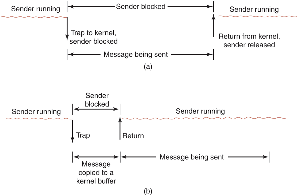
(a) A blocking send call. (b) A nonblocking send call.
An alternative to blocking calls is the use of nonblocking calls (sometimes called asynchronous calls). If send is nonblocking, it returns control to the called immediately, before the message is sent. The advantage of this scheme is that the sending process can continue computing in parallel with the message transmission, instead of having the CPU go idle (assuming no other process is runnable). The choice between blocking and nonblocking primitives is normally made by the system designers (i.e., either one primitive is available or the other), although in a few systems both are available and users can choose their favorite.
However, the performance advantage offered by nonblocking primitives is offset by a serious disadvantage for the programmer: the sender must not modify the message buffer until the message has been sent. The consequences of the process overwriting the message during transmission are too horrible to contemplate. Worse yet, the sending process has no idea of when the transmission is done, so the programmer never knows when it is safe to reuse the buffer. It can hardly avoid touching it forever.
There are three possible ways out. The first solution is to have the kernel copy the message to an internal kernel buffer and then allow the process to continue, as shown in Fig. 8-19(b). From the sender’s point of view, this scheme is the same as a blocking call: as soon as it gets control back, it is free to reuse the buffer. Of course, the message will not yet have been sent, but the sender is not hindered by this fact. The disadvantage of this method is that every outgoing message has to be copied from user space to kernel space. With many network interfaces, the message will have to be copied to a hardware transmission buffer later anyway, so the first copy is essentially wasted. The extra copy can reduce the performance of the system considerably.
The second solution is to interrupt (signal) the sender when the message has been fully sent to inform it that the buffer is once again available. No copy is required here, which saves time, but user-level interrupts make programming tricky, difficult, and subject to race conditions, which makes them irreproducible and nearly impossible to debug.
The third solution is to make the buffer copy on write, that is, to mark it as read only until the message has been sent. If the buffer is reused before the message has been sent, a copy is made. The problem with this solution is that unless the buffer is isolated on its own page, writes to nearby variables will also force a copy. Also, extra administration is needed because the act of sending a message now implicitly affects the read/write status of the page. Finally, sooner or later the page is likely to be written again, triggering a copy that may no longer be necessary.
Thus, the choices on the sending side are
Blocking send (CPU idle during message transmission).
Nonblocking send with copy (CPU time wasted for the extra copy).
Nonblocking send with interrupt (makes programming difficult).
Copy on write (extra copy probably needed eventually).
Under normal conditions, the first choice is the most convenient, especially if multiple threads are available, in which case while one thread is blocked trying to send, one or more other threads can continue working. It also does not require any kernel buffers to be managed. Furthermore, as can be seen from comparing Fig. 8-19(a) to Fig. 8-19(b), the message will usually be out the door faster if no copy is required.
For the record, we would like to point out that some authors use a different criterion to distinguish synchronous from asynchronous primitives. In the alternative view, a call is synchronous only if the sender is blocked until the message has been received and an acknowledgement sent back (Andrews, 1991). In the world of real-time communication, synchronous has yet another meaning, which can lead to confusion, unfortunately.
Just as send can be blocking or nonblocking, so can receive. A blocking call just suspends the caller until a message has arrived. If multiple threads are available, this is a simple approach. Alternatively, a nonblocking receive just tells the kernel where the buffer is and returns control almost immediately. An interrupt can be used to signal that a message has arrived. However, interrupts are difficult to program and are also quite slow, so it may be preferable for the receiver to poll for incoming messages using a procedure, poll, that tells whether any messages are waiting. If so, the called can call get_message, which returns the first arrived message. In some systems, the compiler can insert poll calls in the code at appropriate places, although knowing how often to poll is tricky.
Yet another option is a scheme in which the arrival of a message causes a new thread to be created spontaneously in the receiving process’ address space. Such a thread is called a pop-up thread. It runs a procedure specified in advance and whose parameter is a pointer to the incoming message. After processing the message, it simply exits and is automatically destroyed.
A variant on this idea is to run the receiver code directly in the interrupt handler, without going to the trouble of creating a pop-up thread. To make this scheme even faster, the message itself contains the address of the handler, so when a message arrives, the handler can be called in a few instructions. The big win here is that no copying at all is needed. The handler takes the message from the interface board and processes it on the fly. This scheme is called active messages (Von Eicken et al., 1992). Since each message contains the address of the handler, active messages work only when senders and receivers trust each other completely.
8.2.4 Remote Procedure Call
Although the message-passing model provides a convenient way to structure a multicomputer operating system, it suffers from one incurable flaw: the basic paradigm around which all communication is built is input/output. The procedures send and receive are fundamentally engaged in doing I/O, and many people believe that I/O is the wrong programming model.
This problem has long been known, but little was done about it until a paper by Birrell and Nelson (1984) introduced a completely different way of attacking the problem. Although the idea is refreshingly simple (once someone has thought of it), the implications are often subtle. In this section we will examine the concept, its implementation, its strengths, and its weaknesses.
In a nutshell, what Birrell and Nelson suggested was allowing programs to call procedures located on other CPUs. When a process on machine 1 calls a procedure on machine 2, the calling process on 1 is suspended, and execution of the called procedure takes place on 2. Information can be transported from the called to the callee in the parameters and can come back in the procedure result. No message passing or I/O at all is visible to the programmer. This technique is known as RPC (Remote Procedure Call) and has become the basis of a large amount of multicomputer software. Traditionally the calling procedure is known as the client and the called procedure is known as the server; we will use those names here, too.
The idea behind RPC is to make a remote procedure call look as much as possible like a local one. In the simplest form, to call a remote procedure, the client program must be bound with a small library procedure called the client stub that represents the server procedure in the client’s address space. Similarly, the server is bound with a procedure called the server stub. These procedures hide the fact that the procedure call from the client to the server is not local.
The actual steps in making an RPC are shown in Fig. 8-20. Step 1 is the client calling the client stub. This call is a local procedure call, with the parameters pushed onto the stack in the normal way. Step 2 is the client stub packing the parameters into a message and making a system call to send the message. Packing the parameters is called marshaling. Step 3 is the kernel sending the message from the client machine to the server machine. Step 4 is the kernel passing the incoming packet to the server stub (which would normally have called receive earlier). Finally, step 5 is the server stub calling the server procedure. The reply traces the same path in the other direction.
Figure 8-20
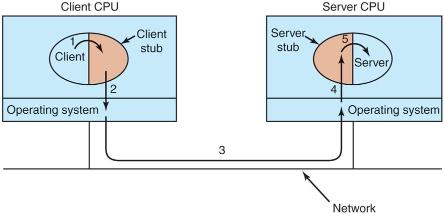
Steps in making a remote procedure call. The stubs are shaded.
The key item to note here is that the client procedure, written by the user, just makes a normal (local) procedure call to the client stub, which has the same name as the server procedure. Since the client procedure and client stub are in the same address space, the parameters are passed in the usual way. Similarly, the server procedure is called by a procedure in its address space with the parameters it expects. To the server procedure, nothing is odd. In this way, instead of doing I/O using send and receive, remote communication is done by faking a procedure call.
Implementation Issues
Despite the conceptual elegance of RPC, there are a few snakes hiding under the grass. A big one is the use of pointer parameters. Normally, passing a pointer to a procedure is not a problem. The called procedure can use the pointer the same way the caller can because the two procedures reside in the same virtual address space. With RPC, passing pointers is impossible because the client and server are in different address spaces.
In some cases, tricks can be used to make it possible to pass pointers. Suppose that the first parameter is a pointer to an integer, k. The client stub can marshal k and send it along to the server. The server stub then creates a pointer to k and passes it to the server procedure, just as it expects. When the server procedure returns control to the server stub, the latter sends k back to the client, where the new k is copied over the old one, just in case the server changed it. In effect, the standard calling sequence of call-by-reference has been replaced by copy restore. Unfortunately, this trick does not always work, for example, if the pointer points to a graph or other complex data structure. For this reason, some restrictions must be placed on parameters to procedures called remotely. Yes, it is easy to construct cases where RPC fails badly, but programmers using it do not want it to fail, so they avoid the cases where it can fail.
A second problem is that in weakly typed languages, like C, it is perfectly legal to write a procedure that computes the inner product of two vectors (arrays), without specifying how large either one is. Each could be terminated by a special value known only to the calling and called procedures. Under these circumstances, it is essentially impossible for the client stub to marshal the parameters: it has no way of determining how large they are.
A third problem is that it is not always possible to deduce the types of the parameters, not even from a formal specification or the code itself. An example is printf, which may have any number of parameters (at least one), and they can be an arbitrary mixture of integers, shorts, longs, characters, strings, floating-point numbers of various lengths, and other types. Trying to call printf as a remote procedure would be practically impossible because C is so permissive. However, a rule saying that RPC can be used provided that you do not program in C (or C++) would not be popular.
A fourth problem relates to the use of global variables. Normally, the calling and called procedures may communicate using global variables, in addition to communicating via parameters. If the called procedure is now moved to a remote machine, the code will fail because the global variables are no longer shared.
These problems are not meant to suggest that RPC is hopeless. In fact, it is widely used, but some restrictions and care are needed to make it work well in practice.
8.2.5 Distributed Shared Memory
Although RPC has its attractions, many programmers still prefer a model of shared memory and would like to use it, even on a multicomputer. Surprisingly enough, it is possible to preserve the illusion of shared memory reasonably well, even when it does not actually exist, using a technique called DSM (Distributed Shared Memory) (Li, 1986; and Li and Hudak, 1989). Despite being an old topic, research on it is still going strong (Ruan et al., 2020; and Wang et al., 2021). DSM is a useful technique to study as it shows many of the issues and complications in distributed systems. Moreover, the idea itself has been very influential. With DSM, each page is located in one of the memories of Fig. 8-1(b). Each machine has its own virtual memory and page tables. When a CPU does a LOAD or STORE on a page it does not have, a trap to the operating system occurs. The operating system then locates the page and asks the CPU currently holding it to unmap the page and send it over the interconnection network. When it arrives, the page is mapped in and the faulting instruction restarted. In effect, the operating system is just satisfying page faults from remote RAM instead of from local disk. To the user, the machine looks as if it has shared memory.
The difference between actual shared memory and DSM is illustrated in Fig. 8-21. In Fig. 8-21(a), we see a true multiprocessor with physical shared memory implemented by the hardware. In Fig. 8-21(b), we see DSM, implemented by the operating system. In Fig. 8-21(c), we see yet another form of shared memory, implemented by yet higher levels of software. We will come back to this third option later in the chapter, but for now we will concentrate on DSM.
Figure 8-21

Various layers where shared memory can be implemented. (a) The hardware. (b) The operating system. (c) User-level software.
Let us now look in some detail at how DSM works. In a DSM system, the address space is divided up into pages, with the pages being spread over all the nodes in the system. When a CPU references an address that is not local, a trap occurs, and the DSM software fetches the page containing the address and restarts the faulting instruction, which now completes successfully. This concept is shown in Fig. 8-22(a) for an address space with 16 pages and 4 nodes, each of them capable of holding 6 pages.
Figure 8-22
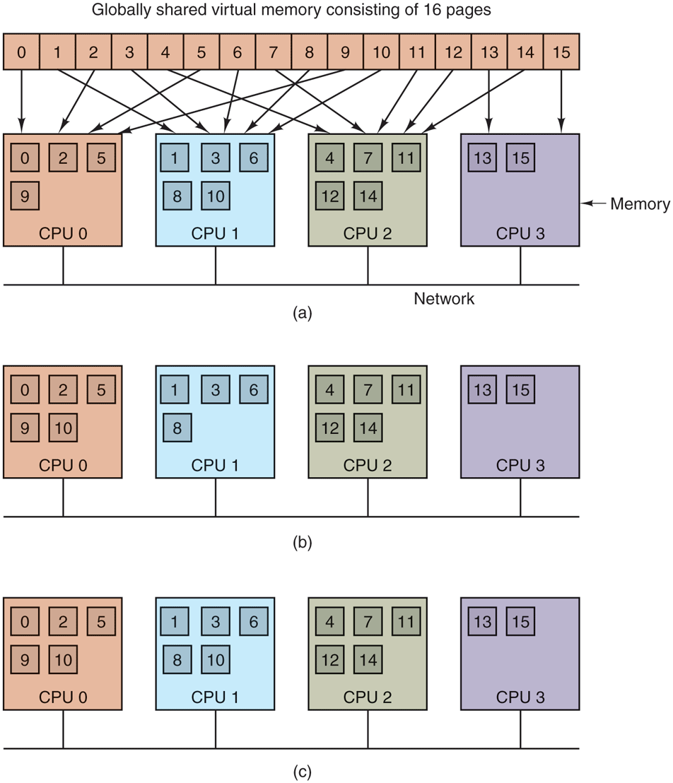
(a) Pages of the address space distributed among four machines. (b) Situation after CPU 0 references page 10 and the page is moved there. (c) Situation if page 10 is read only and replication is used.
In this example, if CPU 0 references instructions or data in pages 0, 2, 5, or 9, the references are done locally. References to other pages cause traps. For example, a reference to an address in page 10 will cause a trap to the DSM software, which then moves page 10 from node 1 to node 0, as shown in Fig. 8-22(b).
Replication
One improvement to the basic system that can improve performance considerably is to replicate pages that are read only, for example, program text, read-only constants, or other read-only data structures. For example, if page 10 in Fig. 8-22 is a section of program text, its use by CPU 0 can result in a copy being sent to CPU 0 without the original in CPU 1’s memory being invalidated or disturbed, as shown in Fig. 8-22(c). In this way, CPUs 0 and 1 can both reference page 10 as often as needed without causing traps to fetch missing memory.
Another possibility is to replicate not only read-only pages, but also all pages. As long as reads are being done, there is effectively no difference between replicating a read-only page and replicating a read-write page. However, if a replicated page is suddenly modified, special action has to be taken to prevent having multiple, inconsistent copies in existence. How inconsistency is prevented will be discussed in the following sections.
False Sharing
DSM systems are similar to multiprocessors in certain key ways. In both systems, when a nonlocal memory word is referenced, a chunk of memory containing the word is fetched from its current location and put on the machine making the reference (main memory or cache, respectively). An important design issue is how big the chunk should be? In multiprocessors, the cache block size is usually 32 or 64 bytes, to avoid tying up the bus with the transfer too long. In DSM systems, the unit has to be a multiple of the page size (because the MMU works with pages), but it can be 1, 2, 4, or more pages. In effect, doing this simulates a larger page size.
There are advantages and disadvantages to a larger page size for DSM. The biggest advantage is that because the startup time for a network transfer is fairly substantial, it does not really take much longer to transfer 4096 bytes than it does to transfer 1024 bytes. By transferring data in large units, when a large piece of address space has to be moved, the number of transfers may often be reduced. This property is especially important because many programs exhibit locality of reference, meaning that if a program has referenced one word on a page, it is likely to reference other words on the same page in the immediate future.
On the other hand, the network will be tied up longer with a larger transfer, blocking other faults caused by other processes. Also, too large an effective page size introduces a new problem, called false sharing, illustrated in Fig. 8-23. Here we have a page containing two unrelated shared variables, A and B. Processor 1 makes heavy use of A, reading and writing it. Similarly, process 2 uses B frequently. Under these circumstances, the page containing both variables will constantly be traveling back and forth between the two machines.
Figure 8-23
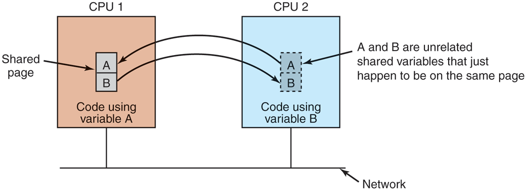
False sharing of a page containing two unrelated variables.
The problem here is that although the variables are unrelated, they appear by accident on the same page, so when a process uses one of them, it also gets the other. The larger the effective page size, the more often false sharing will occur, and conversely, the smaller the effective page size, the less often it will occur. Nothing analogous to this phenomenon is present in ordinary virtual memory systems.
Clever compilers that understand the problem and place variables in the address space accordingly can help reduce false sharing and improve performance. However, saying this is easier than doing it. Furthermore, if the false sharing consists of node 1 using one element of an array and node 2 using a different element of the same array, there is little that even a clever compiler can do to eliminate the problem.
Achieving Sequential Consistency
If writable pages are not replicated, achieving consistency is not an issue. There is exactly one copy of each writable page, and it is moved back and forth dynamically as needed. Since it is not always possible to see in advance which pages are writable, in many DSM systems, when a process tries to read a remote page, a local copy is made and both the local and remote copies are set up in their respective MMUs as read only. As long as all references are reads, everything is fine.
However, if any process attempts to write on a replicated page, a potential consistency problem arises because changing one copy and leaving the others alone is unacceptable. This situation is analogous to what happens in a multiprocessor when one CPU attempts to modify a word that is present in multiple caches. The solution there is for the CPU about to do the write to first put a signal on the bus telling all other CPUs to discard their copy of the cache block. DSM systems typically work the same way. Before a shared page can be written, a message is sent to all other CPUs holding a copy of the page telling them to unmap and discard the page. After all of them have replied that the unmap has finished, the original CPU can now do the write.
It is also possible to tolerate multiple copies of writable pages under carefully restricted circumstances. One way is to allow a process to acquire a lock on a portion of the virtual address space, and then perform multiple read and write operations on the locked memory. At the time the lock is released, changes can be propagated to other copies. As long as only one CPU can lock a page at a given moment, this scheme preserves consistency.
Alternatively, when a potentially writable page is actually written for the first time, a clean copy is made and saved on the CPU doing the write. Locks on the page can then be acquired, the page updated, and the locks released. Later, when a process on a remote machine tries to acquire a lock on the page, the CPU that wrote it earlier compares the current state of the page to the clean copy and builds a message listing all the words that have changed. This list is then sent to the acquiring CPU to update its copy instead of invalidating it (Keleher et al., 1994).
8.2.6 Multicomputer Scheduling
On a multiprocessor, all processes reside in the same memory. When a CPU finishes its current task, it picks a process and runs it. In principle, all processes are potential candidates. On a multicomputer the situation is quite different. Each node has its own memory and its own set of processes. CPU 1 cannot suddenly decide to run a process located on node 4 without first doing a fair amount of work to go get it. This difference means that scheduling on multicomputers is easier but allocation of processes to nodes is more important. Below we will study these issues.
Multicomputer scheduling is somewhat similar to multiprocessor scheduling, but not all of the former’s algorithms apply to the latter. The simplest multiprocessor algorithm—maintaining a single central list of ready processes—does not work however, since each process can only run on the CPU it is currently located on. However, when a new process is created, a choice can be made where to place it, for example, to balance the load.
Since each node has its own processes, any local scheduling algorithm can be used. However, it is also possible to use multiprocessor gang scheduling, since that merely requires an initial agreement on which process to run in which time slot, and some way to coordinate the start of the time slots.
8.2.7 Load Balancing
There is relatively little to say about multicomputer scheduling because once a process has been assigned to a node, any local scheduling algorithm will do, unless gang scheduling is being used. However, precisely because there is so little control once a process has been assigned to a node, the decision about which process should go on which node is important. This is in contrast to multiprocessor systems, in which all processes live in the same memory and can be scheduled on any CPU at will. Consequently, it is worth looking at how processes can be assigned to nodes in an effective way. The algorithms and heuristics for doing this assignment are known as processor allocation algorithms.
A large number of processor (i.e., node) allocation algorithms have been proposed over the years. They differ in what they assume is known and what the goal is. Properties that might be known about a process include the CPU requirements, memory usage, and amount of communication with every other process. Possible goals include minimizing wasted CPU cycles due to lack of local work, minimizing total communication bandwidth, and ensuring fairness to users and processes. Below we will examine a few algorithms to give an idea of what is possible.
A Graph-Theoretic Deterministic Algorithm
A widely studied class of algorithms is for systems consisting of processes with known CPU and memory requirements, and a known matrix giving the average amount of traffic between each pair of processes. If the number of processes is greater than the number of CPUs, k, several processes will have to be assigned to each CPU. The idea is to perform this assignment to minimize network traffic.
The system can be represented as a weighted graph, with each vertex being a process and each arc representing the flow of messages between two processes. Mathematically, the problem then reduces to finding a way to partition (i.e., cut) the graph into k disjoint subgraphs, subject to certain constraints (e.g., total CPU and memory requirements below some limits for each subgraph). For each solution that meets the constraints, arcs that are entirely within a single subgraph represent intramachine communication and can be ignored. Arcs that go from one subgraph to another represent network traffic. The goal is then to find the partitioning that minimizes the network traffic while meeting all the constraints. As an example, Fig. 8-24 shows a system of nine processes, A through I, with each arc labeled with the mean communication load between those two processes (e.g., in Mbps).
Figure 8-24
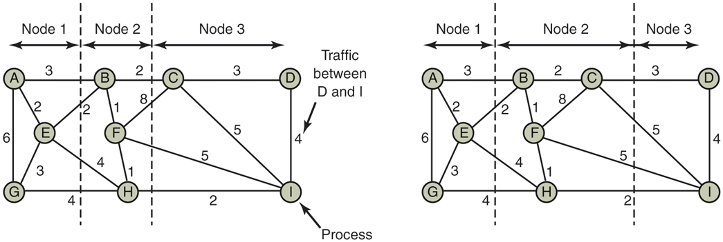
Two ways of allocating nine processes to three nodes.
In Fig. 8-24(a), we have partitioned the graph with processes A, E, and G on node 1, processes B, F, and H on node 2, and processes C, D, and I on node 3. The total network traffic is the sum of the arcs intersected by the cuts (the dashed lines), or 30 units. In Fig. 8-24(b), we have a different partitioning that has only 28 units of network traffic. Assuming that it meets all the memory and CPU constraints, this is a better choice because it requires less communication.
Intuitively, what we are doing is looking for clusters that are tightly coupled (high intracluster traffic flow) but that interact little with other clusters (low intercluster traffic flow). Work on this problem has been going on for over 40 years. Some of the earliest papers discussing the problem are Chow and Abraham (1982), Lo (1984), and Stone and Bokhari (1978).
A Sender-Initiated Distributed Heuristic Algorithm
Now let us look at some distributed algorithms. One algorithm says that when a process is created, it runs on the node that created it unless that node is overloaded. The metric for overloaded might involve too many processes, too big a total working set, or some other metric. If it is overloaded, the node selects another node at random and asks it what its load is (using the same metric). If the probed node’s load is below some threshold value, the new process is sent there (Eager et al., 1986). If not, another machine is chosen for probing. Probing does not go on forever. If no suitable host is found within N probes, the algorithm terminates and the process runs on the originating machine. The idea is for heavily loaded nodes to try to get rid of excess work, as shown in Fig. 8-25(a), which depicts sender-initiated load balancing.
Figure 8-25
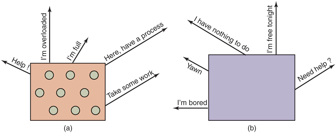
(a) An overloaded node looking for a lightly loaded node to hand off processes to. (b) An empty node looking for work to do.
Eager et al. constructed an analytical queueing model of this algorithm. Using this model, it was established that the algorithm behaves well and is stable under a wide range of parameters, including various threshold values, transfer costs, and probe limits.
Nevertheless, it should be observed that under conditions of heavy load, all machines will constantly send probes to other machines in a futile attempt to find one that is willing to accept more work. Few processes will be off-loaded, but considerable overhead may be incurred in the attempt to do so.
A Receiver-Initiated Distributed Heuristic Algorithm
A complementary algorithm to the one discussed above, which is initiated by an overloaded sender, is one initiated by an underloaded receiver, as shown in Fig. 8-25(b). With this algorithm, whenever a process finishes, the system checks to see if it has enough work. If not, it picks some machine at random and asks it for work. If that machine has nothing to offer, a second, and then a third machine is asked. If no work is found with N probes, the node temporarily stops asking, does any work it has queued up, and tries again when the next process finishes. If no work is available, the machine goes idle. After some fixed time interval, it begins probing again. Having the idle server do the work of probing is best.
An advantage of this algorithm is that it does not put extra load on the system at critical times. The sender-initiated algorithm makes large numbers of probes precisely when the system can least tolerate it—when it is heavily loaded. With the receiver-initiated algorithm, when the system is heavily loaded, the chance of a machine having insufficient work is small. However, when this does happen, it will be easy to find work to take over. Of course, when there is little work to do, the receiver-initiated algorithm creates considerable probe traffic as all the unemployed machines desperately hunt for work. However, it is far better to have the overhead go up when the system is underloaded than when it is overloaded.
It is also possible to combine both of these algorithms and have machines try to get rid of work when they have too much, and try to acquire work when they do not have enough. Furthermore, machines can perhaps improve on random polling by keeping a history of past probes to determine if any machines are chronically underloaded or overloaded. One of these can be tried first, depending on whether the initiator is trying to get rid of work or acquire it.