5.6 User Interfaces: Keyboard, Mouse, & Monitor
Every general-purpose computer has a keyboard and monitor (and sometimes a mouse) to allow people to interact with it. Although the keyboard and monitor are technically separate devices, they work closely together. On mainframes, there are frequently many remote users, each with a device containing a keyboard and an attached display as a unit. These devices have historically been called terminals. People frequently still use that term, even when discussing personal computer keyboards and monitors (mostly for lack of a better term).
5.6.1 Input Software
User input comes primarily from the keyboard and mouse (or sometimes touch screens), so let us look at those. On a personal computer, the keyboard contains an embedded microprocessor which usually interfaces with the motherboard over a USB port (or Bluetooth). In the old days of keyboards connected via serial ports, an interrupt was generated whenever a key was struck and a second one whenever a key was released. At each of these keyboard interrupts, the keyboard driver would extract the information about what happened.
USB keyboards work in a slightly different way and use a so-called interrupt transfer to handle the keystrokes. In spite of its name, an interrupt transfer is not like a regular interrupt at all. To see why, we must dive into USB communication a bit deeper.
USB devices communicate with a USB host controller, typically located on the motherboard, using logical communication channels known as pipes. Each host controller is responsible for one or more USB ports and there may be multiple pipes between the controller and a device. Besides message pipes that are bidirectional and used for control messages (such as simple commands that the host controller sends to the device, or status reports from the device to the host controller), USB offers stream pipes, which are unidirectional data channels. Stream pipes can be used for different types of transfer, such as isochronous transfers (which have a fixed bandwidth), bulk transfers (sporadic, but large transfers which use all the bandwidth they can get, but offer no guarantees), and the interrupt transfers we mentioned earlier. Unlike the other types, interrupt transfers guarantee an upper bound on the latency of the data transfer between the device and the host controller.
In USB, the host controller initiates the interrupt transfer. Thus, although the device can make data available whenever an event occurs, the transfer does not start until the host explicitly requests the data. So how does USB guarantee the latency bound? Simple. The host controller promises to poll for interrupt transfer data within a specific periodic interval. The length of the interval can be specified by the device within the limits that are determined by the type of USB bus. For instance, for a USB 2.0 bus, the device may specify polling intervals in multiples of 125 microseconds between 125 microseconds and 4 seconds.
In the interrupt transfer (i.e., when polled), the USB keyboard will send a report to the controller containing information about key events, such as key presses or key releases. The report has a well-defined format and is up to 8 bytes long, where the first byte contains information about the position of the modifier keys (such as the shift, alt, and control keys), the second byte is reserved, and the remaining six bytes each may contain the scancode of a key that was pressed. In other words, a single report may inform the controller of whole sequence of keys. An example is shown in Fig. 5-30. When the user presses ‘‘H’’ (without any modifiers), the third byte contains the scancode for that key (the hexadecimal value 0x0b). No other keys are pressed so all other bytes are zero. Next, the user presses another key without releasing the first. Now the keyboards sends a report with two scancodes. When the user subsequently releases one of the keys, that value is zeroed out. Moreover, the next scancode shifts to the left. In fact, the order of the bytes indicates the order in which the user pressed the keys. Thus, if the user presses ‘‘O’’ in Step 5, the keyboard’s report indicates not just which keys are currently depressed, but also that ‘‘H’’ was pressed first, then ‘‘B’’ and finally ‘‘O’’. In other words, the bytes further to the left correspond to keys that were pressed earlier and the ones further to the right correspond to later key presses.
Figure 5-30
| Key event | Report | Comment | |
|---|---|---|---|
| 1 | Press (only) “H” | 00 00 0b 00 00 00 00 00 | Scancode for “H” is 0x0b |
| 2 | Press “J” without releasing “H” | 00 00 0b 0d 00 00 00 00 | Scancode for “J” is 0x0d |
| 3 | Press “B” without releasing “HJ” | 00 00 0b 0d 05 00 00 00 | Scancode for “B” is 0x05 |
| 4 | Release “J”, still pressing “HB” | 00 00 0b 05 00 00 00 00 | No press is 0x00 |
| 5 | Press “O” without releasing “HB” | 00 00 0b 05 12 00 00 00 | Scancode for “O” is 0x12 |
Reports sent by a USB keyboard when a user presses and releases different keys. Earlier key presses are encoded by the bytes toward the left.
So far, we described something called an interrupt transfer, but found that we talked only about polling. Where are the interrupts? Remember that the transfer described so far occurred between the USB device (the keyboard) and the host controller. After completely receiving the report, the host controller may now generate the interrupt to tell the CPU the happy news about the key presses. At each of these keyboard interrupts, the keyboard driver extracts the information about what happened. From that point on, everything happens in software and is pretty much independent of the hardware.
Most of the rest of this section can be best understood when thinking of typing commands to a shell window (command-line interface). This is how programmers commonly work. We will discuss graphical interfaces later. Some devices, in particular touch screens, are used for input and output. We have made an (arbitrary) choice to discuss them in the section on output devices. We will discuss graphical interfaces later in this chapter.
Keyboard Software
The numbers in the reports represent the key numbers, called the scan codes, not the ASCII code. When the A key is struck, for example, the scan code (4) is put in the report. It is up to the driver to determine that it is lowercase, uppercase, CTRL-A, ALT-A, CTRL-ALT-A, or some other combination. For instance, the driver can check the first (modifier) byte in the report to see if the SHIFT, CTRL, or ALT keys were pressed.
Two possible philosophies can be adopted for the driver. In the first one, the driver’s job is just to accept input and pass it upward unmodified. A program reading from the keyboard gets a raw sequence of ASCII codes. (Giving user programs the scan codes is too primitive, as well as being highly keyboard dependent.)
This philosophy is well suited to the needs of sophisticated screen editors such as Emacs, which allow the user to bind an arbitrary action to any character or sequence of characters. It does, however, mean that if the user types dste instead of date and then corrects the error by typing three backspaces and ate, followed by a carriage return, the user program will be given all 11 ASCII codes typed, as follows:
d s t e ← ← ← a t e CRNot all programs want this much detail. Often they just want the corrected input, not the exact sequence of how it was produced. This observation leads to the second philosophy: the driver handles all the intraline editing and just delivers corrected lines to the user programs. The first philosophy is character oriented; the second one is line oriented. Originally they were referred to as raw mode and cooked mode, respectively. The POSIX standard uses the less-picturesque term canonical mode to describe line-oriented mode. Noncanonical mode is equivalent to raw mode, although many details of the behavior can be changed. POSIX compatible systems provide several library functions that support selecting either mode and changing many parameters.
If the keyboard is in canonical (cooked) mode, characters must be stored until an entire line has been accumulated, because the user may subsequently decide to erase part of it. Even if the keyboard is in raw mode, the program may not yet have requested input, so the characters must be buffered to allow type ahead. Either a dedicated buffer can be used or buffers can be allocated from a pool. The former puts a fixed limit on type ahead; the latter does not. This issue arises most acutely when the user is typing to a shell window (also known as command-line window) and has just issued a command (such as a compilation) that has not yet completed. Subsequent characters typed have to be buffered because the shell is not ready to read them. System designers who do not permit users to type far ahead ought to be tarred and feathered, or worse yet, forced to use their own system.
Although the keyboard and monitor are logically separate devices, many users have grown accustomed to seeing the characters they have just typed appear on the screen. This process is called echoing.
Echoing is complicated by the fact that a program may be writing to the screen while the user is typing (again, think about typing to a shell window). At the very least, the keyboard driver has to figure out where to put the new input without its being overwritten by program output.
Echoing also gets complicated when more than 80 characters have to be displayed in a window with 80-character lines (or some other number). Depending on the application, wrapping around to the next line may be appropriate. However, some drivers just truncate lines to 80 characters by throwing away all characters beyond column 80.
Another problem is tab handling. It is usually up to the driver to compute where the cursor is currently located, taking into account both output from programs and output from echoing, and compute the proper number of spaces to be echoed.
Now we come to the problem of device equivalence. Logically, at the end of a line of text, one wants a carriage return, to move the cursor back to column 1, and a line feed, to advance to the next line. Requiring users to type both at the end of each line would not sell well. It is up to the device driver to convert whatever comes in to the format used by the operating system. In UNIX, the Enter key is converted to a line feed for internal storage; in Windows it is converted to a carriage return followed by a line feed.
If the standard form is just to store a line feed (the UNIX convention), then carriage returns (created by the Enter key) should be turned into line feeds. If the internal format is to store both (the Windows convention), then the driver should generate a line feed when it gets a carriage return and a carriage return when it gets a line feed. No matter what the internal convention, the monitor may require both a line feed and a carriage return to be echoed in order to get the screen updated properly. On a multiuser system such as a mainframe, different users may have different types of terminals connected to it and it is up to the keyboard driver to get all the different carriage-return/line-feed combinations converted to the internal system standard and arrange for all echoing to be done right.
When operating in canonical mode, some of the input characters have special meanings. Figure 5-31 shows all of the special characters required by the POSIX standard. The defaults are all control characters that should not conflict with text input or codes used by programs; all except the last two can be changed under program control.
Figure 5-31
| Character | POSIX name | Comment |
|---|---|---|
| CTRL-H | ERASE | Backspace one character |
| CTRL-U | KILL | Erase entire line being typed |
| CTRL-V | LNEXT | Interpret next character literally |
| CTRL-S | STOP | Stop output |
| CTRL-Q | START | Start output |
| DEL | INTR | Interrupt process (SIGINT) |
| CTRL-\ | QUIT | Force core dump (SIGQUIT) |
| CTRL-D | EOF | End of file |
| CTRL-M | CR | Carriage return (unchangeable) |
| CTRL-J | NL | Line feed (unchangeable) |
Characters that are handled specially in canonical mode.
The ERASE character allows the user to rub out the character just typed. It is usually the backspace (CTRL-H). It is not added to the character queue but instead removes the previous character from the queue. It should be echoed as a sequence of three characters, backspace, space, and backspace, in order to remove the previous character from the screen. If the previous character was a tab, erasing it depends on how it was processed when it was typed. If it is immediately expanded into spaces, some extra information is needed to determine how far to back up. If the tab itself is stored in the input queue, it can be removed and the entire line just output again. In most systems, backspacing will only erase characters on the current line. It will not erase a carriage return and back up into the previous line.
When the user notices an error at the start of the line being typed in, it is often convenient to erase the entire line and start again. The KILL character erases the entire line. Most systems make the erased line vanish from the screen, but a few older ones echo it plus a carriage return and line feed because some users like to see the old line. Consequently, how to echo KILL is a matter of taste. As with ERASE it is usually not possible to go further back than the current line. When a block of characters is killed, it may or may not be worth the trouble for the driver to return buffers to the pool, if one is used.
Sometimes the ERASE or KILL characters must be entered as ordinary data. The LNEXT character serves as an escape character. In UNIX CTRL-V is the default. As an example, older UNIX systems often used the @ sign for KILL, but the Internet mail system uses addresses of the form linda@cs.washington.edu. Someone who feels more comfortable with older conventions might redefine KILL as @, but then need to enter an @ sign literally to address email. This can be done by typing CTRL-V @. The CTRL-V itself can be entered literally by typing CTRL-V twice consecutively. After seeing a CTRL-V, the driver sets a flag saying that the next character is exempt from special processing. The LNEXT character itself is not entered in the character queue.
To allow users to stop a screen image from scrolling out of view, control codes are provided to freeze the screen and restart it later. In UNIX these are STOP, (CTRL-S) and START, (CTRL-Q), respectively. They are not stored but are used to set and clear a flag in the keyboard data structure. Whenever output is attempted, the flag is inspected. If it is set, no output occurs. Usually, echoing is also suppressed along with program output.
It is often necessary to kill a runaway program being debugged. The INTR (DEL) and QUIT (CTRL-\) characters can be used for this purpose. In UNIX, DEL sends the SIGINT signal to all the processes started up from that keyboard. Implementing DEL can be quite tricky because UNIX was designed from the beginning to handle multiple users at the same time. Thus, in the general case, there may be many processes running on behalf of many users, and the DEL key must signal only the user’s own processes. The hard part is getting the information from the driver to the part of the system that handles signals, which, after all, has not asked for this information.
CTRL-\ is similar to DEL, except that it sends the SIGQUIT signal, which forces a core dump if not caught or ignored. When either of these keys is struck, the driver should echo a carriage return and line feed and discard all accumulated input to allow for a fresh start. The default value for INTR is often CTRL-C instead of DEL, since many programs use DEL interchangeably with the backspace for editing.
Another special character is EOF (CTRL-D), which in UNIX causes any pending read requests for the terminal to be satisfied with whatever is available in the buffer, even if the buffer is empty. Typing CTRL-D at the start of a line causes the program to get a read of 0 bytes, which is conventionally interpreted as end-of-file and causes most programs to act the same way as they would upon seeing end-of-file on an input file.
Mouse Software
Most desktop PCs have a mouse, or sometimes a trackball, which is just a mouse lying on its back. Notebooks usually have a trackpad, but some people use a mouse with them instead. Whenever a mouse has moved a certain minimum distance in either direction or a button is pressed or released, a message is sent to the computer. The minimum distance is about 0.1 mm (although it can be set in software). Some people call this unit a mickey. Mice (or occasionally, mouses) can have one, two, or three buttons, depending on the designers’ estimate of the users’ intellectual ability to keep track of more than one button. Some mice have wheels that can send additional data back to the computer. Wireless mice are the same as wired mice except that instead of sending their data back to the computer over a wire, they use low-power radios, for example, using the Bluetooth standard.
The message to the computer contains three items: buttons. The first item is the change in x position since the last message. Then comes the change in y position since the last message. Finally, the status of the buttons is included. The format of the message depends on the system and the number of buttons the mouse has. Usually, it takes 3 bytes. Most mice report back a maximum of 40 times/sec, so the mouse may have moved multiple mickeys since the last report.
Note that the mouse indicates only changes in position, not absolute position itself. If the mouse is picked up and put down gently, no messages will be sent.
Many GUIs distinguish between single clicks and double clicks of a mouse button. If two clicks are close enough in space (mickeys) and also close enough in time (milliseconds), a double click is signaled. The maximum for ‘‘close enough’’ is up to the software, with both parameters usually being user settable.
Trackpads
Notebook computers are generally equipped with a trackpad (also called a touchpad), for moving the cursor around the screen. Trackpads commonly also have buttons around the edge, which are used like mouse buttons. Some trackpads do not have buttons, but pressing the trackpad down hard acts like a button press. Apple MacBooks work this way.
There are two kinds of trackpads in common use. The first one uses conductive sensing. With these devices there is a series of very fine parallel wires running from the front edge of the device toward the screen. Below it is an insulating layer. Below that is another set of very fine wires running perpendicular to the other set, from left to right. In some devices the layers are reversed.
When the user presses down on the trackpad, the gap between them gets smaller, allowing electricity to flow at the contact point. The hardware in the trackpad can detect this and pass the coordinates where contact is made to the device driver.
The other kind of trackpad uses capacitance. This type is more common in modern notebooks. In this system, tiny capacitors are constantly charging and discharging. When a finger touches the surface, the capacitance increases locally at the point where the finger is and the hardware outputs the coordinates to the driver. For this type of trackpad, pressing it with a pencil, pen, eraser, or piece of plastic has no effect because these objects do not have capacitance, as the human body does. So if you want to write all over your trackpad with a pen, you can (although we do not recommend it), but doing so will not move the cursor. As a homework exercise, try licking your trackpad. It should move the cursor as tongues have capacitance.
The touch screens used on smartphones are similar to trackpads. We will discuss them later in this chapter.
5.6.2 Output Software
Now let us consider output software. First we will look at simple output to a text window, which is what programmers normally prefer to use. Then we will consider graphical user interfaces, which other users often prefer.
Text Windows
Output is simpler than input when the output is sequentially in a single font, size, and color. For the most part, the program sends characters to the current window and they are displayed there. Usually, a block of characters, for example, a line, is written in one system call.
Screen editors and many other sophisticated programs need to be able to update the screen in complex ways such as replacing one line in the middle of the screen. To accommodate this need, most output drivers support a series of commands to move the cursor, insert and delete characters or lines at the cursor, and so on. These commands are often called escape sequences. In the heyday of the simple text-only ASCII terminal, there were hundreds of terminal types, each with its own escape sequences. As a consequence, it was difficult to write software that worked on more than one terminal type.
One solution, which was introduced in Berkeley UNIX, was a terminal database called termcap. This software package defined a number of basic actions, such as moving the cursor to (row, column). To move the cursor to a particular location, the software, say, an editor, used a generic escape sequence which was then converted to the actual escape sequence for the terminal being written to. In this way, the editor worked on any terminal that had an entry in the termcap database. Much UNIX software still works this way, even on personal computers.
Eventually, the industry saw the need for standardizing the escape sequence, so an ANSI standard was developed. Some of the values are shown in Fig. 5-32.
Figure 5-32
| Escape sequence | Meaning |
|---|---|
| ESC [ n A | Move up n lines |
| ESC [ n B | Move down n lines |
| ESC [ n c | Move right n spaces |
| ESC [ n D | Move left n spaces |
| ESC [ m; n H | Move cursor to (m,n) |
| ESC [ s J | Clear screen from cursor (0 to end, 1 from start, 2 all) |
| ESC [ s K | Clear line from cursor (0 to end, 1 from start, 2 all) |
| ESC [n L | Insert n lines at cursor |
| ESC [ n M | Delete n lines at cursor |
| ESC [ n P | Delete n chars at cursor |
| ESC [n @ | Insert n chars at cursor |
| ESC [ n m | Enable rendition n ( ) |
| ESC M | Scroll the screen backward if the cursor is on the top line |
The ANSI escape sequences accepted by the terminal driver on output. ESC denotes the ASCII escape character (0x1B), and n, m, and s are optional numeric parameters.
Consider how these escape sequences might be used by a text editor. Suppose that the user types a command telling the editor to delete all of line 3 and then close up the gap between lines 2 and 4. The editor might send the following escape sequence over the serial line to the terminal:
ESC [3; 1 H ESC [0 K ESC [1 M(where the spaces are used above only to separate the symbols; they are not transmitted). This sequence moves the cursor to the start of line 3, erases the entire line, and then deletes the now-empty line, causing all the lines starting at 5 to move up one line. Then what was line 4 becomes line 3; what was line 5 becomes line 4, and so on. Analogous escape sequences can be used to add text to the middle of the display. Words can be added or removed in a similar way.
The X Window System
Nearly all UNIX systems base their user interface on the X Window System (often just called X), developed at M.I.T. as part of project Athena in the 1980s. It is very portable and runs entirely in user space. It was originally intended for connecting a large number of remote user terminals with a central compute server, so it is logically split into client software and host software, which can potentially run on different computers. On modern personal computers, both parts can run on the same machine. On Linux systems, the popular Gnome and KDE desktop environments run on top of X.
When X is running on a machine, the software that collects input from the keyboard and mouse and writes output to the screen is called the X server. It has to keep track of which window is currently selected (where the mouse pointer is), so it knows which client to send any new keyboard input to. It communicates with running programs (usually over a network) called X clients. It sends them keyboard and mouse input and accepts display commands from them.
It may seem odd that the X server is always inside the user’s computer while the X client may be off on a remote compute server, but just think of the X server’s main job: displaying bits on the screen, so it makes sense to be near the user. From the program’s point of view, it is a client telling the server to do things, like display text and geometric figures. The server (in the local PC) just does what it is told, as do all servers.
The arrangement of client and server is shown in Fig. 5-33 for the case where the X client and X server are on different machines. But when running Gnome or KDE on a single machine, the client is just some application program using the X library talking to the X server on the same machine (but using a TCP connection over sockets, the same as it would do in the remote case).
Figure 5-33
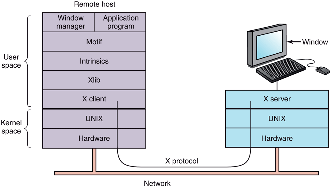
Clients and servers in the M.I.T. X Window System.
The reason it is possible to run the X Window System on top of UNIX (or another operating system) on a single machine or over a network is that what X really defines is the X protocol between the X client and the X server, as shown in Fig. 5-33. It does not matter whether the client and server are on the same machine, separated by 100 meters over a local area network, or are thousands of kilometers apart and connected by the Internet. The protocol and operation of the system is identical in all cases.
X is just a windowing system. It is not a complete GUI. To get a complete GUI, others layer of software are run on top of it. One layer is Xlib, which is a set of library procedures for accessing the X functionality. These procedures form the basis of the X Window System and are what we will examine below, but they are too primitive for most user programs to access directly. For example, each mouse click is reported separately, so that determining that two clicks really form a double click has to be handled above Xlib.
To make programming with X easier, a toolkit consisting of the Intrinsics is supplied as a part of X. This layer manages buttons, scroll bars, and other GUI elements, called widgets. To make a true GUI interface, with a uniform look and feel, another layer is needed (or several of them). One example is Motif, shown in Fig. 5-33, which is the basis of the Common Desktop Environment used on Solaris and other commercial UNIX systems Most applications make use of calls to Motif rather than Xlib. Gnome and KDE have a similar structure to Fig. 5-33, only with different libraries. Gnome uses the GTK+ library and KDE uses the Qt library. Whether having two GUIs is better than one is debatable.
Also worth noting is that window management is not part of X itself. The decision to leave it out was fully intentional. Instead, a separate X client process, called a window manager, controls the creation, deletion, and movement of windows on the screen. To manage windows, it sends commands to the X server telling it what to do. It often runs on the same machine as the X client, but in theory can run anywhere. There have been over a hundred window managers for UNIX written and many are still in active use. Some were designed to be lean and mean, while others add fancy 3D graphics or try to create a look and feel of Windows on UNIX. For hardcore fans of the Emacs editors, there is even the Emacs X Window Manager, written in Lisp, that is sure to blow the minds of their misguided vi friends.
Window managers control the appearance and placement of windows. On top of the window manager, most people use a desktop environment such as GNOME or KDE. The desktop environment provides a pre-configured, pleasant working environment that is more deeply integrated with applications, for instance with respect to drag-and-drop functionality, panels, and sidebars.
This modular design, consisting of several layers and multiple programs, makes X highly portable and flexible. It has been ported to most versions of UNIX, including Solaris, all variants of BSD, AIX, Linux, and so on, making it possible for application developers to have a standard user interface for multiple platforms. It has also been ported to other operating systems. In contrast, in Windows, the windowing and GUI systems are mixed together in the GDI and located in the kernel, which makes them harder to maintain, and of, course, not portable.
Now let us take a brief look at X as viewed from the Xlib level. When an X program starts, it opens a connection to one or more X servers—let us call them workstations even though they might be collocated on the same machine as the X program itself. X considers this connection to be reliable in the sense that lost and duplicate messages are handled by the networking software and it does not have to worry about communication errors. Usually, TCP/IP is used between the client and server.
Four kinds of messages go over the connection:
Drawing commands from the program to the workstation.
Replies by the workstation to program queries.
Keyboard, mouse, and other event announcements.
Error messages.
Most drawing commands are sent from the program to the workstation as oneway messages. No reply is expected. The reason for this design is that when the client and server processes are on different machines, it may take a substantial period of time for the command to reach the server and be carried out. Blocking the application program during this time would slow it down unnecessarily. On the other hand, when the program needs information from the workstation, it simply has to wait until the reply comes back.
Like Windows, X is highly event driven. Events flow from the workstation to the program, usually in response to some human action such as keyboard strokes, mouse movements, or a window being uncovered. Each event message is 32 bytes, with the first byte giving the event type and the next 31 bytes providing additional information. Several dozen kinds of events exist, but a program is sent only those events that it has said it is willing to handle. For example, if a program does not want to hear about key releases, it is not sent any key-release events. As in Windows, events are queued, and programs read events from the input queue. However, unlike Windows, the operating system never calls procedures within the application program on its own. It does not even know which procedure handles which event.
A key concept in X is the resource. A resource is a data structure that holds certain information. Application programs create resources on workstations. Resources can be shared among multiple processes on the workstation. Resources tend to be short-lived and do not survive workstation reboots. Typical resources include windows, fonts, colormaps (color palettes), pixmaps (bitmaps), cursors, and graphic contexts. The latter are used to associate properties with windows and are similar in concept to device contexts in Windows.
A rough, incomplete skeleton of an X program is shown in Fig. 5-34. It begins by including some required headers and then declaring some variables. It then connects to the X server specified as the parameter to XOpenDisplay. Then it allocates a window resource and stores a handle to it in win. In practice, some initialization would happen here. After that it tells the window manager that the new window exists so the window manager can manage it.
Figure 5-34

A skeleton of an X Window application program.
The call to XCreateGC creates a graphic context in which properties of the window are stored. In a more complete program, they might be initialized here. The next statement, the call to XSelectInput, tells the X server which events the program is prepared to handle. In this case it is interested in mouse clicks, keystrokes, and windows being uncovered. In practice, a real program would be interested in other events as well. Finally, the call to XMapRaised maps the new window onto the screen as the uppermost window. At this point, the window becomes visible on the screen.
The main loop consists of two statements and is logically much simpler than the corresponding loop in Windows. The first statement here gets an event and the second one dispatches on the event type for processing. When some event indicates that the program has finished, running is set to 0 and the loop terminates. Before exiting, the program releases the graphic context, window, and connection.
It is worth mentioning that not everyone likes a GUI. Many programmers prefer a traditional command-line oriented interface of the type discussed in Sec. 5.6.1 above. X handles this via a client program called xterm. This program emulates a venerable VT102 intelligent terminal, complete with all the escape sequences. Thus editors such as vi and Emacs and other software that uses termcap work in these windows without modification.
Graphical User Interfaces
Most personal computers offer a GUI (Graphical User Interface). The acronym GUI is pronounced ‘‘gooey.’’
The GUI was invented by Douglas Engelbart and his research group at the Stanford Research Institute. It was then copied by researchers at Xerox PARC. One fine day, Steve Jobs, cofounder of Apple, was touring PARC and saw a GUI on a Xerox computer and said something to the effect of ‘‘Holy mackerel. This is the future of computing.’’ The GUI gave him the idea for a new computer, which became the Apple Lisa. The Lisa was too expensive and was a commercial failure, but its successor, the Macintosh, was a huge success.
When Microsoft got a Macintosh prototype so it could develop Microsoft Office on it, it begged Apple to license the interface to all comers for a fee so it would become the new industry standard. (Microsoft made much more money from Office than from MS-DOS, so it was willing to abandon MS-DOS to have a better platform for Office.) The Apple executive in charge of the Macintosh, JeanLouis Gasse´e, refused and Steve Jobs was no longer around to overrule him. Eventually, Microsoft got a license for elements of the interface. This formed the basis of Windows. When Windows began to catch on, Apple sued Microsoft, claiming Microsoft had exceeded the license, but the judge disagreed and Windows went on to overtake the Macintosh. If Gasse´e had agreed with the many people within Apple who also wanted to license the Macintosh software to everyone under the sun, Apple would have become insanely rich on licensing fees alone and Windows would not exist now. Of course, Apple has not done so badly since.
Leaving aside touch-enabled interfaces for the moment, a GUI has four essential elements, denoted by the characters WIMP. These letters stand for Windows, Icons, Menus, and Pointing device, respectively. Windows are rectangular blocks of screen area used to run programs. Icons are little symbols that can be clicked on to cause some action to happen. Menus are lists of actions from which one can be chosen. Finally, a pointing device is a mouse, trackball, or other hardware device used to move a cursor around the screen to select items.
The GUI software can be implemented in either user-level code, as is done in UNIX systems, or in the operating system itself, as in the case in Windows.
Input for GUI systems still uses the keyboard and mouse, but output almost always goes to a special hardware board called a graphics card. A graphics adapter contains a special memory called video RAM that holds the images that appear on the screen. Graphics adapters often have a powerful GPU (Graphics Processing Unit) with 8–16 GB (or more) of their own RAM, separate from the computer’s main memory.
Each graphics adapter supports some number of screen sizes. Common sizes are and However, there are also displays offering higher resolutions (say, or ). Higher resolutions are intended to be used on widescreen monitors whose 16:9 aspect ratio matches them exactly. At a resolution of just (the size of full HD videos), a color display with 24 bits/pixel requires about 6.2 MB of RAM just to hold the image, so with 8 GB, the graphics adapter can hold 1380 images at once. If the full screen is refreshed 60 times/sec, the video RAM must be capable of delivering data continuously at 372 MB/sec. Of course, 4K video is so it needs four times as much storage and bandwidth.
Output software for GUIs is a massive topic. Many 1500-page books have been written about the Windows GUI alone (e.g., Petzold, 2013; Rector and Newcomer, 1997; and Simon, 1997). Clearly, in this section, we can only scratch the surface and present a few of the underlying concepts. To make the discussion concrete, we will describe the Win32 API, which is supported by all 32-bit and 64-bit versions of Windows. The output software for other GUIs is roughly comparable in a general sense, but the details are very different.
The basic item on the screen is a rectangular area called a window. A window’s position and size are uniquely determined by giving the coordinates (in pixels) of two diagonally opposite corners. A window may contain a title bar, a menu bar, a tool bar, a vertical scroll bar, and a horizontal scroll bar. A typical window is shown in Fig. 5-35. Note that the Windows coordinate system puts the origin in the upper left-hand corner and has y increase downward, which is different from the Cartesian coordinates used in mathematics.
Figure 5-35
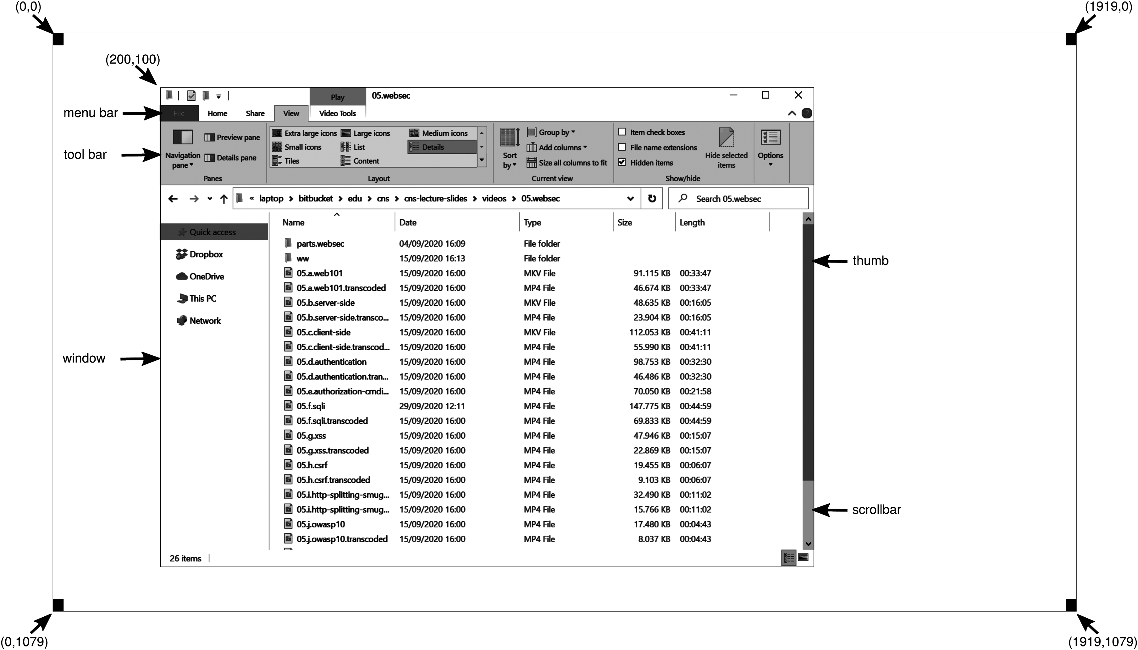
A sample window on the authors’ machine on a display.
When a window is created, the parameters specify whether it can be moved by the user, resized by the user, or scrolled (by dragging the thumb on the scroll bar) by the user. The main window produced by most programs can be moved, resized, and scrolled, which has enormous consequences for the way Windows programs are written. In particular, programs must be informed about changes to the size of their windows and must be prepared to redraw the contents of their windows at any time, even when they least expect it.
As a consequence, Windows programs are message oriented. User actions involving the keyboard or mouse are captured by Windows and converted into messages to the program owning the window being addressed. Each program has a message queue to which messages relating to all its windows are sent. The main loop of the program consists of fishing out the next message and processing it by calling an internal procedure for that message type. In some cases, Windows itself may call these procedures directly, bypassing the message queue. This model is quite different from the UNIX model of procedural code that makes system calls to interact with the operating system. X, however, is also event oriented.
To make this programming model clearer, consider the example of Fig. 5-36. Here we see the skeleton of a main program for Windows. It is not complete and does no error checking, but it shows enough detail for our purposes. It starts by including a header file, windows.h, which contains many macros, data types, constants, function prototypes, and other information needed by Windows programs.
Figure 5-36
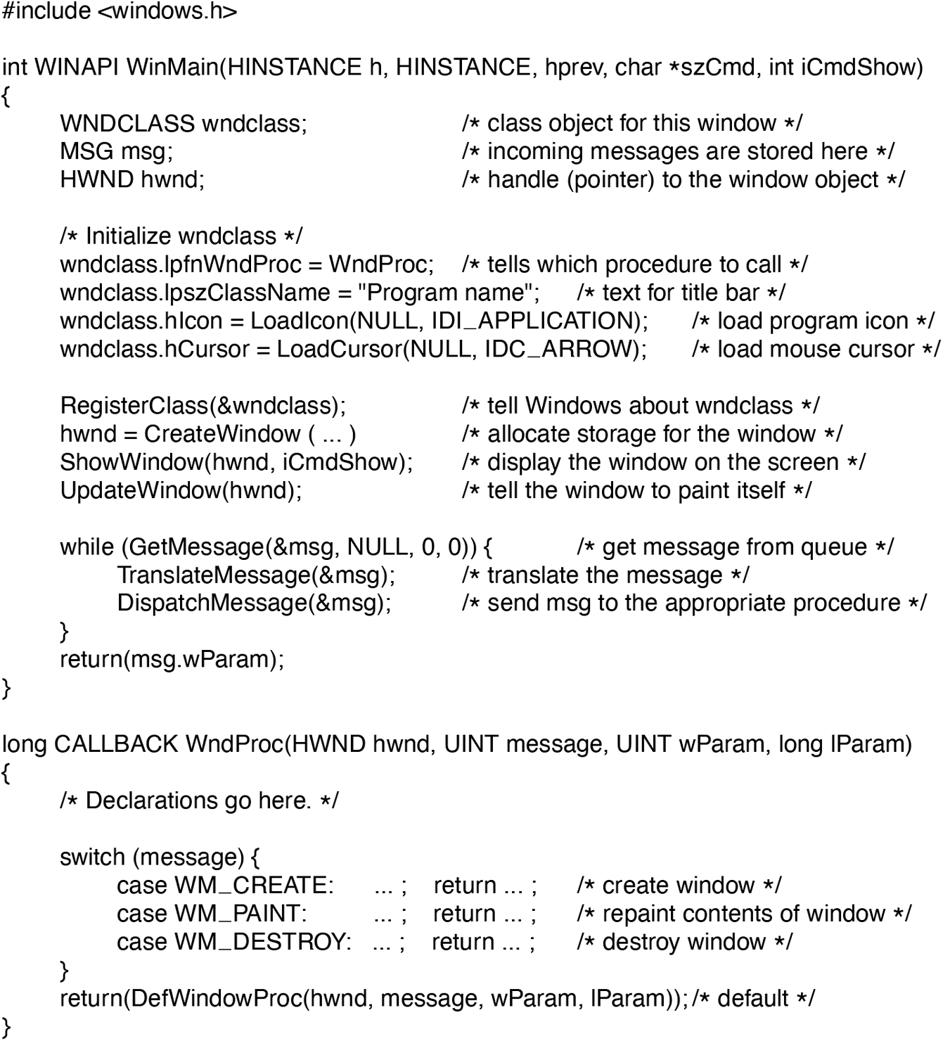
A skeleton of a Windows main program.
The main program starts with a declaration giving its name and parameters. The WINAPI macro is an instruction to the compiler to use a certain parameter-passing convention and will not be of further concern to us. The first parameter, h, is an instance handle and is used to identify the program to the rest of the system. To some extent, Win32 is object oriented, which means that the system contains objects (e.g., programs, files, and windows) that have some state and associated code, called methods, that operate on that state. Objects are referred to using handles, and in this case, h identifies the program. The second parameter is present only for reasons of backward compatibility. It is no longer actually used. The third parameter, szCmd, is a zero-terminated string containing the command line that started the program, even if it was not started from a command line. The fourth parameter, iCmdShow, tells whether the program’s initial window should occupy the entire screen, part of the screen, or none of the screen (task bar only).
This declaration illustrates a widely used Microsoft convention called Hungarian notation. The name is a play on Polish notation, the postfix system invented by the Polish logician J. Lukasiewicz for representing algebraic formulas without using precedence or parentheses. Hungarian notation was invented by a Hungarian programmer at Microsoft, Charles Simonyi, who was the main architect of Microsoft Word and Excel. It uses the first few characters of an identifier to specify the type. The allowed letters and types include c (character), w (word, now meaning an unsigned 16-bit integer), i (32-bit signed integer), l (long, also a 32-bit signed integer), s (string), sz (string terminated by a zero byte), p (pointer), fn (function), and h (handle). Thus szCmd is a zero-terminated string and iCmdShow is an integer, for example. Many programmers believe that encoding the type in variable names this way has little value and makes Windows code hard to read. Also, things get hairy if you port your code from a 32-bit system to a 64-bit one, where parameters are suddenly 64 bits but their names still have the old i or l suffix. Nothing analogous to this convention is present in UNIX.
Every window must have an associated class object that defines its properties. In Fig. 5-36, that class object is wndclass. An object of type WNDCLASS has 10 fields, four of which are initialized in Fig. 5-36. In an actual program, the other six would be initialized as well. The most important field is lpfnWndProc, which is a long (i.e., 32-bit) pointer to the function that handles the messages directed to this window. The other fields initialized here tell which name and icon to use in the title bar, and which symbol to use for the mouse cursor.
After wndclass has been initialized, RegisterClass is called to pass it to Windows. In particular, after this call Windows knows which procedure to call when various events occur that do not go through the message queue. The next call, CreateWindow, allocates memory for the window’s data structure and returns a handle for referencing it later. The program then makes two more calls in a row, to put the window’s outline on the screen, and finally fill it in completely.
At this point we come to the program’s main loop, which consists of getting a message, having certain translations done to it, and then passing it back to Windows to have Windows invoke WndProc to process it. To answer the question of whether this whole mechanism could have been made simpler, the answer is yes, but it was done this way for historical reasons and we are now stuck with it.
Following the main program is the procedure WndProc, which handles the various messages that can be sent to the window. The use of CALLBACK here, like WINAPI above, specifies the calling sequence to use for parameters. The first parameter is the handle of the window to use. The second parameter is the message type. The third and fourth parameters can be used to provide additional information when needed.
Message types WM_CREATE and WM_DESTROY are sent at the start and end of the program, respectively. They give the program the opportunity, for example, to allocate memory for data structures and then return it.
The third message type, WM_PAINT, is an instruction to the program to fill in the window. It is called not only when the window is drawn the first time, but also possibly during program execution as well. In contrast to text-based systems, in Windows a program cannot assume that whatever it draws on the screen will stay there until it removes it. Other windows can be dragged on top of this one, menus can be pulled down over it, dialog boxes and tool tips can cover part of it, and so on. When these items are removed, the window has to be redrawn. The way Windows tells a program to redraw a window is to send it a WM_PAUS message. As a friendly gesture, it also provides information about what part of the window has been overwritten, in case it is easier or faster to regenerate that part of the window instead of redrawing the whole thing from scratch.
There are two ways Windows can get a program to do something. One way is to post a message to its message queue. This method is used for keyboard input, mouse input, and timers that have expired. The other way, sending a message to the window, involves having Windows directly call WndProc itself. This method is used for all other events. Since Windows is notified when a message is fully processed, it can refrain from making a new call until the previous one is finished. In this way race conditions are avoided.
There are many more message types. To avoid erratic behavior should an unexpected message arrive, the program should call DefWindowProc at the end of WndProc to let the default handler take care of the other cases.
In summary, a Windows program normally creates one or more windows with a class object for each one. Associated with each program is a message queue and a set of handler procedures. Ultimately, the program’s behavior is driven by the incoming events, which are processed by the handler procedures. This is a very different model of the world than the more procedural view that UNIX takes.
Drawing to the screen is handled by a package consisting of hundreds of procedures that are bundled together to form the GDI (Graphics Device Interface). It can handle text and graphics and is designed to be platform and device independent. Before a program can draw (i.e., paint) in a window, it needs to acquire a device context, which is an internal data structure containing properties of the window, such as the font, text color, background color, and so on. Most GDI calls use the device context, either for drawing or for getting or setting the properties.
Various ways exist to acquire the device context. A simple example of its acquisition and use is
hdc = GetDC(hwnd);TextOut(hdc, x, y, psText, iLength);ReleaseDC(hwnd, hdc);
The first statement gets a handle to a device content, hdc. The second one uses the device context to write a line of text on the screen, specifying the (x, y) coordinates of where the string starts, a pointer to the string itself, and its length. The third call releases the device context to indicate that the program is through drawing for the moment. Note that hdc is used in a way analogous to a UNIX file descriptor. Also note that ReleaseDC contains redundant information (the use of hdc uniquely specifies a window). The use of redundant information that has no actual value is common in Windows.
Another interesting note is that when hdc is acquired in this way, the program can write only in the client area of the window, not in the title bar and other parts of it. Internally, in the device context’s data structure, a clipping region is maintained. Any drawing outside the clipping region is ignored. However, there is another way to acquire a device context, GetWindowDC, which sets the clipping region to the entire window. Other calls restrict the clipping region in other ways. Having multiple calls that do almost the same thing is characteristic of Windows.
A complete treatment of the GDI is out of the question here. For the interested reader, the references cited above provide additional information. Nevertheless, given how important it is, a few words about the GDI are probably worthwhile. GDI has various procedure calls to get and release device contexts, obtain information about device contexts, get and set device context attributes (e.g., the background color), and manipulate GDI objects such as pens, brushes, and fonts, each of which has its own attributes. Finally, of course, there are a large number of GDI calls to actually draw on the screen.
The drawing procedures fall into four categories: drawing lines and curves, drawing filled areas, managing bitmaps, and displaying text. We saw an example of drawing text above, so let us take a quick look at one of the others. The call
Rectangle(hdc, xleft, ytop, xright, ybottom);draws a filled rectangle whose corners are (xleft, ytop) and (xright, ybottom). For example,
Rectangle(hdc, 2, 1, 6, 4);will draw the rectangle shown in Fig. 5-37. The line width and color and fill color are taken from the device context. Other GDI calls are similar in flavor.
Figure 5-37
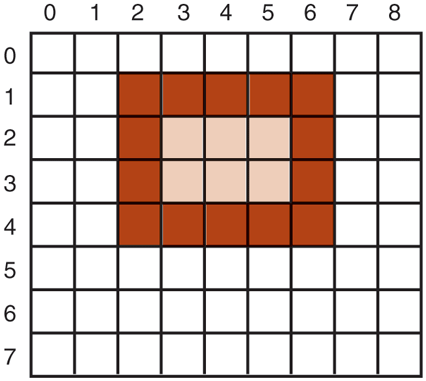
An example rectangle drawn using Rectangle. Each box represents one pixel.
Bitmaps
The GDI procedures are examples of vector graphics. They are used to place geometric figures and text on the screen. They can be scaled easily to larger or smaller screens (provided the number of pixels on the screen is the same). They are also relatively device independent.
Not all the images that computers manipulate can be generated using vector graphics. Photographs and videos, for example, do not use vector graphics. Instead, these items are scanned in by overlaying a grid on the image. The average red, green, and blue values of each grid square are then sampled and saved as the value of one pixel. Such a file is called a bitmap. There are extensive facilities in Windows for manipulating bitmaps.
Another use for bitmaps is for text. One way to represent a particular character in some font is as a small bitmap. Adding text to the screen then becomes a matter of moving bitmaps. One general way to use bitmaps is through a procedure called BitBlt. It is called as follows:
BitBlt(dsthdc, dx, dy, wid, ht, srchdc, sx, sy, rasterop);In its simplest form, it copies a bitmap from a rectangle in one window to a rectangle in another window (or the same one). The first three parameters specify the destination window and position. Then come the width and height. Next come the source window and position. Note that each window has its own coordinate system, with (0, 0) in the upper left-hand corner of the window. The last parameter will be described below. The effect of
BitBlt(hdc2, 1, 2, 5, 7, hdc1, 2, 2, SRCCOPY);is shown in Fig. 5-38. Notice carefully that the entire area of the letter A has been copied, including the background color.
Figure 5-38
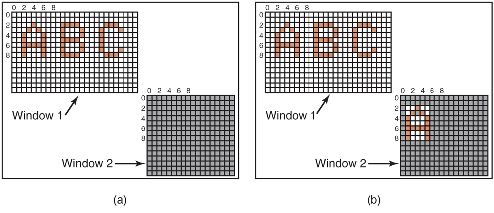
Copying bitmaps using BitBlt. (a) Before. (b) After.
BitBlt can do more than just copy bitmaps. The last parameter gives the possibility of performing Boolean operations to combine the source bitmap and the destination bitmap. For example, the source can be ORed into the destination to merge with it. It can also be EXCLUSIVE ORed into it, which maintains the characteristics of both source and destination.
A problem with bitmaps is that they do not scale. A character that is in a box of on a display of will look reasonable. However, if this bitmap is copied to a printed page at 1200 dots/inch, which is the character width (8 pixels) will be 8/1200 inch or 0.17 mm. In addition, copying between devices with different color properties or between monochrome and color does not work well.
For this reason, Windows also supports a data structure called a DIB (Device Independent Bitmap). Files using this format use the extension .bmp. These files have file and information headers and a color table before the pixels. This information makes it easier to move bitmaps between dissimilar devices.
Fonts
In versions of Windows before 3.1, characters were represented as bitmaps and copied onto the screen or printer using BitBlt. The problem with that, as we just saw, is that a bitmap that makes sense on the screen is too small for the printer. Also, a different bitmap is needed for each character in each size. In other words, given the bitmap for A in 10-point type, there is no way to compute it for 12-point type. Because every character of every font might be needed for sizes ranging from 4 point to 120 point, a vast number of bitmaps were needed. The whole system was just too cumbersome for text.
The solution was the introduction of TrueType fonts, which are not bitmaps but outlines of the characters. Each TrueType character is defined by a sequence of points around its perimeter. All the points are relative to the (0, 0) origin. Using this system, it is easy to scale the characters up or down. All that has to be done is to multiply each coordinate by the same scale factor. In this way, a TrueType character can be scaled up or down to any point size, even fractional point sizes. Once at the proper size, the points can be connected using the well-known follow-thedots algorithm taught in kindergarten (note that modern kindergartens use splines for smoother results). After the outline has been completed, the character can be filled in. An example of some characters scaled to three different point sizes is given in Fig. 5-39.
Figure 5-39
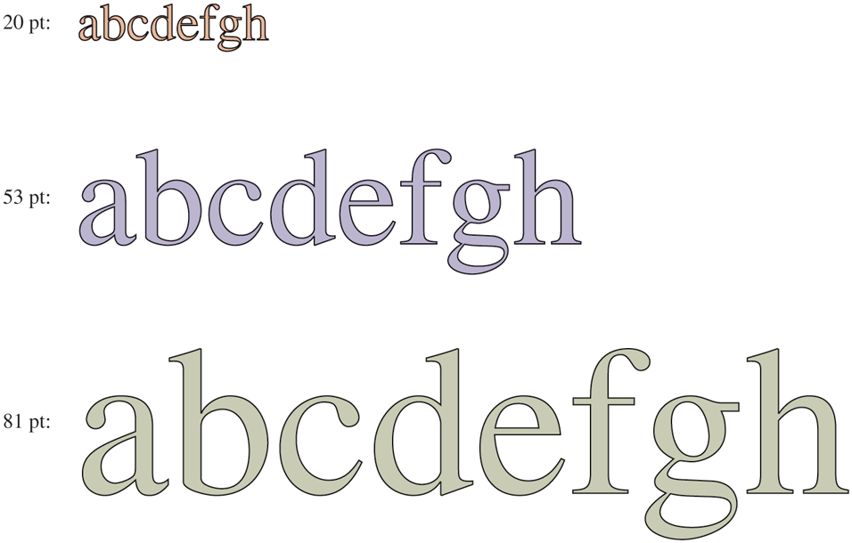
Some examples of character outlines at different point sizes.
Once the filled character is available in mathematical form, it can be rasterized, that is, converted to a bitmap at whatever resolution is desired. By first scaling and only then rasterizing, we can be sure that the characters displayed on the screen or printed on the printer will be as close as possible, differing only in quantization error. To improve the quality still more, it is now possible to embed hints in each character telling how to do the rasterization. For example, both serifs on the top of the letter T should be identical, something that might not otherwise be the case due to roundoff error. Hints improve the final appearance.
Touch Screens
More and more the screen is used as an input device also. Especially on smartphones, tablets, and other portable devices, it is convenient to tap and swipe away at the screen with your finger (or a stylus). The user experience is different and more intuitive than with a mouse-like device, since the user interacts directly with the objects on the screen. Research has shown that even orangutans are capable of operating touch-based devices.
A touch device is not necessarily a screen. Touch devices fall into two categories: opaque and transparent. A typical opaque touch device is the trackpad on a notebook computer, as discussed earlier. An example of a transparent device is the touch screen on a smartphone or tablet. In this section, however, we limit ourselves to touch screens.
Like many things that have come into fashion in the computer industry, touch screens are not exactly new. As early as 1965, E.A. Johnson of the British Royal Radar Establishment described a (capacitive) touch display that, while crude, served as precursor of the displays we find today. Most modern touch screens are either resistive or capacitive.
Resistive screens have a flexible plastic surface on top. The plastic in itself is nothing too special, except that is more scratch resistant than your garden variety plastic. However, a thin film of ITO (Indium Tin Oxide) or some similar conducive material) is printed in thin lines onto the surface’s underside. Beneath it, but not quite touching it, is a second surface also coated with a layer of ITO. On the top surface, the charge runs in the vertical direction and there are conductive connections at the top and bottom. In the bottom layer the charge runs horizontally and there are connections on the left and right. When you touch the screen, you dent the plastic so that the top layer of ITO touches the bottom layer. To find out the exact position of the finger or stylus touching it, all you need to do is measure the resistance in both directions at all the horizontal positions of the bottom and all the vertical positions of the top layer.
Capacitive Screens have two hard surfaces, typically glass, each coated with ITO. A typical configuration is to have ITO added to each surface in parallel lines, where the lines in the top layer are perpendicular to those in the bottom layer. For instance, the top layer may be coated in thin lines in a vertical direction, while the bottom layer has a similarly striped pattern in the horizontal direction. The two charged surfaces, separated by air, form a grid of really small capacitors. Voltages are applied alternately to the horizontal and vertical lines, while the voltage values, which are affected by the capacitance of each intersection, are read out on the other ones. When you put your finger onto the screen, you change the local capacitance. By very accurately measuring the minuscule voltage changes everywhere, it is possible to discover the location of the finger on the screen. This operation is repeated many times per second with the coordinates touched fed to the device driver as a stream of (x, y) pairs. Further processing, such as determining whether pointing, pinching, expanding, or swiping is taking place is done by the operating system.
What is nice about resistive screens is that the pressure determines the outcome of the measurements. In other words, it will work even if you are wearing gloves in cold weather. This is not true of capacitive screens, unless you wear special gloves. For instance, you can sew a conductive thread (like silver-plated nylon) through the fingertips of the gloves, or if you are not a needling person, buy them ready-made. Alternatively, you cut off the tips of your gloves and be done in 10 seconds.
What is not so nice about resistive screens is that they typically cannot support multitouch, a technique that detects multiple touches at the same time. It allows you to manipulate objects on the screen with two or more fingers. People (and perhaps also orangutans) like multitouch because it enables them to use pinch-and-expand gestures with two fingers to enlarge or shrink a picture or document. Imagine that the two fingers are at (3, 3) and (8, 8). As a result, the resistive screen may notice a change in resistance on the and vertical lines, and the and horizontal lines. Now consider a different scenario with the fingers at (3, 8) and (8, 3), which are the opposite corners of the rectangle whose corners are (3, 3), (8, 3), (8, 8), and (3, 8). The resistance in precisely the same lines has changed, so the software has no way of telling which of the two scenarios holds. This problem is called ghosting. Because capacitive screens send a stream of (x, y) coordinates, they are more adept at supporting multitouch.
Manipulating a touch screen with just a single finger is still fairly WIMPy— you just replace the mouse pointer with your stylus or index finger. Multitouch is a bit more complicated. Touching the screen with five fingers is like pushing five mouse pointers across the screen at the same time and clearly changes things for the window manager. Multitouch screens have become ubiquitous and increasingly sensitive and accurate. Nevertheless, it is unclear whether the Five Point Palm Exploding Heart Technique has any effect on the CPU.