5.3 I/O Software Layers
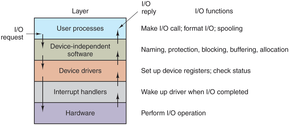
I/O software is typically organized in four layers, as shown in Fig. 5-11. Each layer has a well-defined function to perform and a well-defined interface to the adjacent layers. The functionality and interfaces differ from system to system, so the discussion that follows, which examines all the layers starting at the bottom, is not specific to one machine.
Figure 5-11
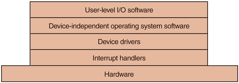
Layers of the I/O software system.
5.3.1 Interrupt Handlers
While programmed I/O is occasionally useful, for most I/O, interrupts are an unpleasant fact of life and cannot be avoided. They should be hidden away, deep in the bowels of the operating system, so that as little of the operating system as possible knows about them. The best way to hide them is to have the driver starting an I/O operation block until the I/O has completed and the interrupt occurs. The driver can block itself, for example, by doing a down on a semaphore, a wait on a condition variable, a receive on a message, or something similar.
When the interrupt happens, the interrupt procedure does whatever it has to in order to handle the interrupt. Then it can unblock the driver that was waiting for it. In some cases it will just complete up on a semaphore. In others, it will do a signal on a condition variable in a monitor. In still others, it will send a message to the blocked driver. In all cases, the net effect of the interrupt will be that a driver that was previously blocked will now be able to run. This model works best if drivers are structured as processes (either in kernel mode or user mode), with their own states, stacks, and program counters.
Of course, reality is not quite so simple. Processing an interrupt is not just a matter of taking the interrupt, doing an up on some semaphore, and then executing an IRET instruction to return from the interrupt to the previous process. There is a great deal more work involved for the operating system. We will now give an outline of this work as a series of steps that must be performed in software after the hardware interrupt discussed earlier has completed. It should be noted that the details are highly system dependent, so some of the steps listed below may not be needed on a particular machine, and steps not listed may be required. Also, the steps that do occur may be in a different order on some machines.
Save any registers (including the PSW) that have not already been saved by the interrupt hardware.
Set up a context for the interrupt-service procedure. Doing this may involve setting up the TLB, MMU, and a page table.
Set up a stack for the interrupt service-procedure.
Acknowledge the interrupt controller. If there is no centralized interrupt controller, reenable interrupts.
Copy the registers from where they were saved (possibly some stack) to the process table.
Run the interrupt-service procedure. Typically, it will extract information from the interrupting device controller’s registers.
Choose which process to run next. If the interrupt has caused some high-priority process that was blocked to become ready, it may be chosen to run now.
Set up the MMU context for the process to run next. Some TLB setup may also be needed.
Load the new process’ registers, including its PSW.
Start running the new process.
As can be seen, interrupt processing is far from trivial. It also takes a considerable number of CPU instructions, especially on machines in which virtual memory is present and page tables have to be set up or the state of the MMU stored (e.g., the R and M bits). On some machines, the TLB and CPU cache may also have to be managed when switching between user and kernel modes, which takes additional machine cycles if many entries need to be purged.
5.3.2 Device Drivers
Earlier in this chapter we looked at what device controllers do. We saw that each controller has some device registers used to give it commands or some device registers used to read out its status or both. The number of device registers and the nature of the commands vary radically from device to device. For example, a mouse driver has to accept information from the mouse telling it how far it has moved and which buttons are currently depressed. In contrast, a disk driver may have to know all about sectors, tracks, cylinders, heads, arm motion, motor drives, head settling times, and all the other mechanics of making the disk work properly. Obviously, these drivers will be very different.
Consequently, each I/O device attached to a computer needs some device-specific code for controlling it. This code, called the device driver, is generally written by the device’s manufacturer and delivered along with the device. Since each operating system needs its own drivers, device manufacturers commonly supply drivers for several popular operating systems.
Each device driver normally handles one device type, or at most, one class of closely related devices. For example, a SATA disk driver can usually handle multiple SATA SSDs and SATA disks of different sizes and different speeds. On the other hand, a mouse and joystick are so different that different drivers are usually required. However, there is no technical restriction on having one device driver control multiple unrelated devices. It is just not a good idea in most cases.
Sometimes though, wildly different devices are based on the same underlying technology. The best-known example is probably USB (Universal Serial Bus). It is not called ‘‘universal’’ for nothing. USB devices include disks, mice, memory sticks, cameras, keyboards, mini-fans, robots, credit card readers, bar code scanners, rechargeable shavers, paper shredders, disco balls, and thermometers. They all use USB and yet they all do very different things. The trick is that USB drivers are typically stacked, like a TCP/IP stack in networks. At the bottom, typically in hardware, we find the USB link layer (serial I/O) that handles hardware stuff like signaling and decoding a stream of signals to USB packets. It is used by higher layers that deal with the data packets and the common functionality for USB that is shared by most devices. On top of that, finally, we find the higher-layer APIs such as the interfaces for mass storage, cameras, etc. Thus, we still have separate device drivers, even though they share part of the protocol stack.
In order to access the device’s hardware, meaning the controller’s registers, the device driver normally has to be part of the operating system kernel, at least with current architectures. Actually, it is possible to construct drivers that run in user space, with system calls for reading and writing the device registers. This design isolates the kernel from the drivers and the drivers from each other, eliminating a major source of system crashes—buggy drivers that interfere with the kernel in one way or another. For building highly reliable systems, this is definitely a good way to go. An example of a system in which the device drivers run as user processes is MINIX 3 (www.minix3.org). However, since most other desktop operating systems run their drivers in the kernel, that is the model we will consider here.
Since the designers of every operating system know that pieces of code (drivers) written by outsiders will be installed in it, it needs to have an architecture that allows such installation. This means having a well-defined model of what a driver does and how it interacts with the rest of the operating system. Device drivers are normally positioned below the rest of the operating system, as is illustrated in Fig. 5-12.
Figure 5-12
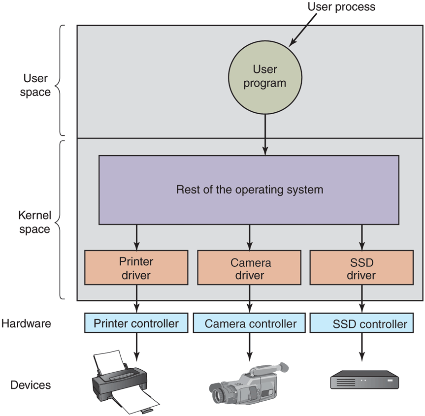
Logical positioning of device drivers. In reality, all communication between drivers and device controllers goes over the bus.
Operating systems usually classify drivers into one of a small number of categories. The most common categories are the block devices, such as disks, which contain multiple data blocks that can be addressed independently, and the character devices, such as keyboards and printers, which generate or accept a stream of characters.
Most operating systems define a standard interface that all block drivers must support and a second standard interface that all character drivers must support. These interfaces consist of a number of procedures that the rest of the operating system can call to get the driver to do work for it. Typical procedures are those to read a block (block device) or write a character string (character device).
In some systems, the operating system is a single binary program that contains all of the drivers it will need compiled into it. This scheme was the norm for years with UNIX systems because they were run by computer centers and I/O devices rarely changed. If a new device was added, the system administrator simply recompiled the kernel with the new driver to build a new binary.
With the advent of personal computers, with their myriad I/O devices, this model no longer worked. Few users are capable of recompiling or relinking the kernel, even if they have the source code or object modules, which is not always the case. Instead, operating systems, starting with MS-DOS, went over to a model in which drivers were dynamically loaded into the system during execution. Different systems handle loading drivers in different ways.
A device driver has several functions. The most obvious one is to accept abstract read and write requests from the device-independent software above it and see that they are carried out. But there are also a few other functions it must perform. For example, the driver must initialize the device, if needed. It may also need to manage its power requirements and log events.
Many device drivers have a similar general structure. A typical driver starts out by checking the input parameters to see if they are valid. If not, an error is returned. If they are valid, a translation from abstract to concrete terms may be needed. For a disk driver, this may mean converting a linear block number into the head, track, sector, and cylinder numbers for the disk’s geometry, while for SSDs the block number should be mapped on the appropriate flash block and page.
Next the driver may check if the device is currently in use. If it is, the request will be queued for later processing. If the device is idle, the hardware status will be examined to see if the request can be handled now. It may be necessary to switch the device on or start a motor before transfers can be begun. On inkjet printers, the print head has to do a little dance before it can start printing. Once the device is on and ready to go, the actual control can begin.
Controlling the device means issuing a sequence of commands to it. The driver is the place where the command sequence is determined, depending on what has to be done. After the driver knows which commands it is going to issue, it starts writing them into the controller’s device registers. After each command is written to the controller, it may be necessary to check to see if the controller accepted the command and is prepared to accept the next one. This sequence continues until all the commands have been issued. Some controllers can be given a linked list of commands (in memory) and told to read and process them all by itself without further help from the operating system.
After the commands have been issued, one of two situations will apply. In many cases, the device driver must wait until the controller does some work for it, so it blocks itself until the interrupt comes in to unblock it. In other cases, however, the operation finishes without delay, so the driver does not need to block. As an example of the latter situation, scrolling the screen requires just writing a few bytes into the controller’s registers. No mechanical motion is needed, so the entire operation can be completed in nanoseconds.
In the former case, the blocked driver will be awakened by the interrupt. In the latter case, it will never go to sleep. Either way, after the operation has been completed, the driver must check for errors. If everything is all right, the driver may have some data to pass to the device-independent software (e.g., a block just read). Finally, it returns some status information for error reporting back to its caller. If any other requests are queued, one of them can now be selected and started. If nothing is queued, the driver blocks waiting for the next request.
This simple model is only a rough approximation to reality. Many factors make the code much more complicated. For one thing, an I/O device may complete while a driver is running, interrupting the driver. The interrupt may cause a device driver to run. In fact, it may cause the current driver to run. For example, while the network driver is processing an incoming packet, another packet may arrive. Consequently, drivers have to be reentrant, meaning that a running driver has to expect that it will be called a second time before the first call has completed.
In a hot-pluggable system, devices can be added or removed while the computer is running. As a result, while a driver is busy reading from some device, the system may inform it that the user has suddenly removed that device from the system. Not only must the current I/O transfer be terminated without damaging any kernel data structures, but any pending requests for the now-vanished device must also be gracefully removed from the system and their callers given the bad news. Furthermore, the unexpected addition of new devices may cause the kernel to juggle resources (e.g., interrupt request lines), taking old ones away from the driver and giving it new ones in their place.
Drivers are not allowed to make system calls, but they often need to interact with the rest of the kernel. Usually, calls to certain kernel procedures are permitted. For example, there are usually calls to allocate and deallocate hardwired pages of memory for use as buffers. Other useful calls are needed to manage the MMU, timers, the DMA controller, the interrupt controller, and so on.
5.3.3 Device-Independent I/O Software
Although some of the I/O software is device specific, other parts of it are device independent. The exact boundary between the drivers and the device-independent software is system (and device) dependent, because some functions that could be done in a device-independent way may actually be done in the drivers, for efficiency or other reasons. The functions shown in Fig. 5-13 are typically done in the device-independent software.
Figure 5-13
| Uniform interfacing for device drivers |
| Buffering |
| Error reporting |
| Allocating and releasing dedicated devices |
| Providing a device-independent block size |
Functions of the device-independent I/O software.
The basic function of the device-independent software is to perform the I/O functions that are common to all devices and to provide a uniform interface to the user-level software. We will now look at the above issues in more detail.
Uniform Interfacing for Device Drivers
A major issue in an operating system is how to make all I/O devices and drivers look more or less the same. If disks, printers, keyboards, and so on, are all interfaced in different ways, every time a new device comes along, the operating system must be modified for the new device. Having to hack on the operating system for each new device is not a good idea.
One aspect of this issue is the interface between the device drivers and the rest of the operating system. In Fig. 5-14(a), we illustrate a situation in which each device driver has a different interface to the operating system. What this means is that the driver functions available for the system to call differ from driver to driver. It might also mean that the kernel functions that the driver needs also differ from driver to driver. Taken together, it means that interfacing each new driver requires a lot of new programming effort.
Figure 5-14
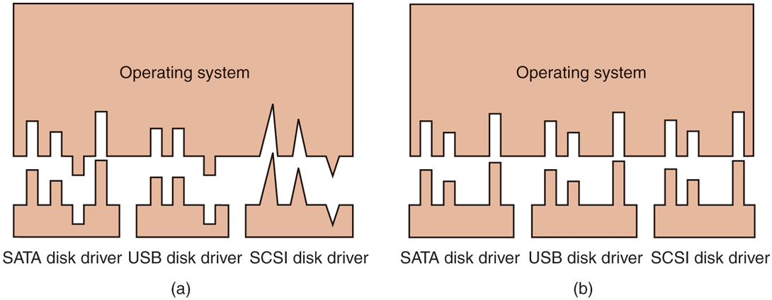
(a) Without a standard driver interface. (b) With a standard driver interface.
In contrast, in Fig. 5-14(b), we show a different design in which all drivers have the same interface. Now it becomes much easier to plug in a new driver, providing it conforms to the driver interface. It also means that driver writers know what is expected of them. In practice, not all devices are absolutely identical, but usually there are only a small number of device types and even these are generally almost the same, or the differ in only minor ways.
The way this works is as follows. For each class of devices, such as disks or printers, the operating system defines a set of functions that the driver must supply. For a disk these would naturally include read and write, but also turning the power on and off, formatting, and other disky things. Often the driver holds a table with pointers into itself for these functions. When the driver is loaded, the operating system records the address of this table of function pointers, so when it needs to call one of the functions, it can make an indirect call via this table. This table of function pointers defines the interface between the driver and the rest of the operating system. All devices of a given class (disks, printers, etc.) must obey it.
Another aspect of having a uniform interface is how I/O devices are named. The device-independent software takes care of mapping symbolic device names onto the proper driver. For example, in UNIX a device name, such as /dev/disk0, uniquely specifies the i-node for a special file, and this i-node contains the major device number, which is used to locate the appropriate driver. The i-node also contains the minor device number, which is passed as a parameter to the driver in order to specify the unit to be read or written. All devices have major and minor numbers, and all drivers are accessed by using the major device number to select the driver.
Closely related to naming is protection. How does the system prevent users from accessing devices that they are not entitled to access? In both UNIX and Windows, devices appear in the file system as named objects, which means that the usual protection rules for files also apply to I/O devices. The system administrator can then set the proper permissions for each device.
Buffering
Buffering is also an issue, both for block and character devices, for a variety of reasons. To see one of them, consider a process that wants to read data from an (VDSL—Very High Bitrate Digital Subscriber Line) modem, something many people use at home to connect to the Internet. One possible strategy for dealing with the incoming characters is to have the user process do a read system call and block waiting for one character. Each arriving character causes an interrupt. The interrupt-service procedure hands the character to the user process and unblocks it. After putting the character somewhere, the process reads another character and blocks again. This model is indicated in Fig. 5-15(a).
Figure 5-15
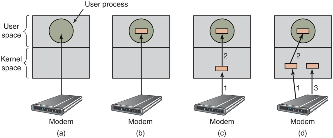
(a) Unbuffered input. (b) Buffering in user space. (c) Buffering in the kernel followed by copying to user space. (d) Double buffering in the kernel.
The trouble with this way of doing business is that the user process has to be started up for every incoming character. Allowing a process to run many times for short runs is inefficient, so this design is not a good one.
An improvement is shown in Fig. 5-15(b). Here the user process provides an n-character buffer in user space and does a read of n characters. The interrupt-service procedure puts incoming characters in this buffer until it is completely full. Only then does it wakes up the user process. This scheme is far more efficient than the previous one, but it has a drawback: what happens if the buffer is paged out when a character arrives? The buffer could be locked in memory, but if many processes start locking pages in memory willy nilly, the pool of available pages will shrink and performance will degrade.
Yet another approach is to create a buffer inside the kernel and have the interrupt handler put the characters there, as shown in Fig. 5-15(c). When this buffer is full, the page with the user buffer is brought in, if needed, and the buffer copied there in one operation. This scheme is far more efficient.
However, even this improved scheme suffers from a problem: What happens to characters that arrive while the page with the user buffer is being brought in from the disk? Since the buffer is full, there is no place to put them. A way out is to have a second kernel buffer. After the first buffer fills up, but before it has been emptied, the second one is used, as shown in Fig. 5-15(d). When the second buffer fills up, it is available to be copied to the user (assuming the user has asked for it). While the second buffer is being copied to user space, the first one can be used for new characters. In this way, the two buffers take turns: while one is being copied to user space, the other is accumulating new input. A buffering scheme like this is called double buffering.
Another common form of buffering is the circular buffer. It consists of a region of memory and two pointers. One pointer points to the next free word, where new data can be placed. The other pointer points to the first word of data in the buffer that has not been removed yet. In many situations, the hardware advances the first pointer as it adds new data (e.g., just arriving from the network) and the operating system advances the second pointer as it removes and processes data. Both pointers wrap around, going back to the bottom when they hit the top.
Buffering is also important on output. Consider, for example, how output is done to the modem without buffering using the model of Fig. 5-15(b). The user process executes a write system call to output n characters. The system has two choices at this point. It can block the user until all the characters have been written, but this could take a very long time over a slow telephone line. It could also release the user immediately and do the I/O while the user computes some more, but this leads to an even worse problem: how does the user process know that the output has been completed and it can reuse the buffer? The system could generate a signal or software interrupt, but that style of programming is difficult and prone to race conditions. A much better solution is for the kernel to copy the data to a kernel buffer, analogous to Fig. 5-15(c) (but the other way), and unblock the caller immediately. Now it does not matter when the actual I/O has been completed. The user is free to reuse the buffer the instant it is unblocked.
Buffering is a widely used technique, but it has a downside as well. If data get buffered too many times, performance suffers. Consider, for example, the network of Fig. 5-16. When a user performs a system call to write to the network, the kernel copies the packet to a kernel buffer to allow the user to proceed immediately (step 1). At this point, the user program can reuse the buffer.
Figure 5-16
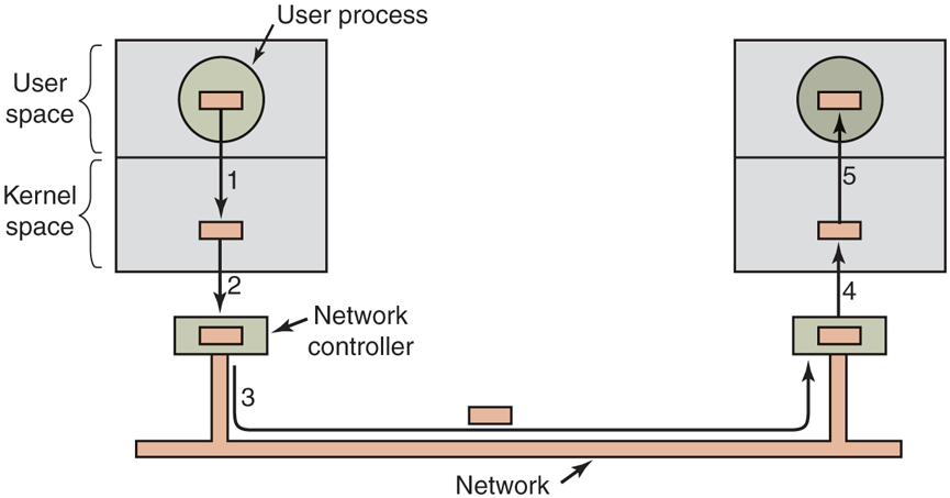
Networking may involve many copies of a packet.
When the driver is called, it copies the data to the controller for output (step 2). The reason it does not output to the wire directly from kernel memory is that once a packet transmission has been started, it must continue at a uniform speed. The driver cannot guarantee that it can get to memory at a uniform speed because DMA channels and other I/O devices may be stealing many cycles. Failing to get a word transmitted on time would ruin the packet. By buffering the packet inside the controller, this problem is avoided.
After the packet has been copied to the controller’s internal buffer, it is copied out onto the network (step 3). Bits arrive at the receiver shortly after being sent, so just after the last bit has been sent, that bit arrives at the receiver, where the packet has been buffered in the controller. Next the packet is copied to the receiver’s kernel buffer (step 4). Finally, it is copied to the receiving process’ buffer (step 5). Usually, the receiver then sends back an acknowledgement. When the sender gets the acknowledgement, it is free to send the next packet. However, it should be clear that all this copying is going to slow down the transmission rate considerably because all the steps must happen sequentially.
Error Reporting
Errors are far more common in the context of I/O than in other contexts. When they occur, the operating system must handle them as best it can. Many errors are device specific and must be handled by the appropriate driver, but the framework for error handling is device independent.
One class of I/O errors is programming errors. These occur when a process asks for something impossible, such as writing to an input device (keyboard, scanner, mouse, etc.) or reading from an output device (printer, plotter, etc.). Other errors are providing an invalid buffer address or other parameter, and specifying an invalid device (e.g., drive 3 when the system has only two drives), and so on. The action to take on these errors is straightforward: just report back an error code to the caller.
Another class of errors is the class of actual I/O errors, for example, trying to write a block that has been damaged or trying to read from a camera that has been switched off. In these circumstances, it is up to the driver to determine what to do. If the driver does not know what to do, it may pass the problem back up to device-independent software.
What this software does depends on the environment and the nature of the error. If it is a simple read error and there is an interactive user available, it may display a dialog box asking the user what to do. The options may include retrying a certain number of times, ignoring the error, or killing the calling process. If there is no user available, probably the only real option is to have the system call fail with an error code.
However, some errors cannot be handled this way. For example, a critical data structure, such as the root directory or free block list, may have been destroyed. In this case, the system may have to display an error message and terminate. There is not much else it can do.
Allocating and Releasing Dedicated Devices
Some devices, such as printers, can be used only by a single process at any given moment. It is up to the operating system to examine requests for device usage and accept or reject them, depending on whether the requested device is available or not. A simple way to handle these requests is to require processes to perform opens on the special files for devices directly. If the device is unavailable, the open fails. Closing such a dedicated device then releases it.
An alternative approach is to have special mechanisms for requesting and releasing dedicated devices. An attempt to acquire a device that is not available blocks the caller instead of failing. Blocked processes are put on a queue. Sooner or later, the requested device becomes available and the first process on the queue is allowed to acquire it and continue execution.
Device-Independent Block Size
Different SSDs have different flash page sizes, while different disks may have different sector sizes. It is up to the device-independent software to hide this fact and provide a uniform block size to higher layers, for example, by treating several sectors or flash pages as a single logical block. In this way, the higher layers deal only with abstract devices that all use the same logical block size, independent of the physical sector size. Similarly, some character devices deliver their data one byte at a time (e.g., mice), while others deliver theirs in larger units (e.g., Ethernet interfaces). These differences may also be hidden.
5.3.4 User-Space I/O Software
Although most of the I/O software is within the operating system, a small portion of it consists of libraries linked together with user programs, and even whole programs running outside the kernel. System calls, including the I/O system calls, are normally made by library procedures. When a C program contains the call
count = write(fd, buffer, nbytes);the library procedure write might be linked with the program and contained in the binary program present in memory at run time. In other systems, libraries can be loaded during program execution. Either way, the collection of all these library procedures is clearly part of the I/O system.
While most of these procedures do little more than put their parameters in the appropriate place for the system call, other I/O procedures actually do real work. In particular, formatting of input and output is done by library procedures. One example from C is printf, which takes a format string and possibly some variables as input, builds an ASCII string, and then calls write to output the string. As an example of printf, consider the statement
printf("The square of %3d is %6d\n", i, i*i);It formats a string consisting of the 14-character string ‘‘The square of ’’ followed by the value i as a 3-character string, then the 4-character string ‘‘ is ’’, then as 6 characters, and finally a line feed.
An example of a similar procedure for input is scanf, which reads input and stores it into variables described in a format string using the same syntax as printf. The standard I/O library contains a number of procedures that involve I/O and all run as part of user programs.
Not all user-level I/O software consists of library procedures. Another important category is the spooling system. Spooling is a way of dealing with dedicated I/O devices in a multiprogramming system. Consider a typical spooled device: a printer. Although it would be technically easy to let any user process open the character special file for the printer, suppose a process opened it and then did nothing for hours. No other process could print anything.
Instead what is done is to create a special process, called a daemon, and a special directory, called a spooling directory. To print a file, a process first generates the entire file to be printed and puts it in the spooling directory. It is up to the daemon, which is the only process having permission to use the printer’s special file, to print the files in the directory. By protecting the special file against direct use by users, the problem of having someone keeping it open unnecessarily long is eliminated.
Figure 5-17 summarizes the I/O system, showing all the layers and the principal functions of each layer. Starting at the bottom, the layers are the hardware, interrupt handlers, device drivers, device-independent software, and finally the user processes.
Figure 5-17
Layers of the I/O system and the main functions of each layer.
The arrows in Fig. 5-17 show the flow of control. When a user program tries to read a block from a file, for example, the operating system is invoked to carry out the call. The device-independent software looks for it, say, in the buffer cache. If the needed block is not there, it calls the device driver to issue the request to the hardware to go get it from the SSD or disk. The process is then blocked until this operation has been completed and the data are safely available in the caller’s buffer. The operation may take milliseconds, which is too long for the CPU to be idle.
When the SSD or disk is finished, the hardware generates an interrupt. The interrupt handler is run to discover what has happened, that is, which device wants attention right now. It then extracts the status from the device and wakes up the sleeping process to finish off the I/O request and let the user process continue.