Long description
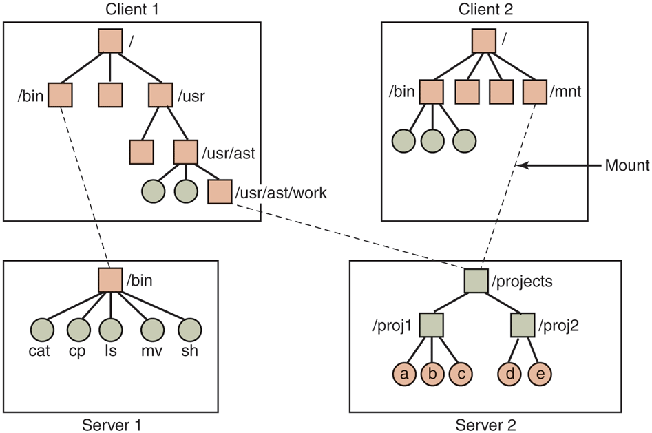
The figure shows four square blocks labeled Client 1, Client 2, Server 1, and Server 2. Client 1 consists of a tree that starts with a square block labeled slash that is connected to three square blocks, the first block is labeled slash bin, and the third block is labeled slash usr. The slash use block is connected to two blocks, the second block is labeled slash usr slash ast, this block is connected to two circles and one square block that is labeled slash usr slash ast slash work. The Client 2 block is consist of a tree that starts with a square block labeled slash that is connected to four blocks, the first block is labeled slash bin, and the fourth block is labeled slash mnt. The slash bin block is connected to three circles. The Server 1 block is consist of a tree that starts with a square block labeled slash bin that is connected to five circles labeled cat, cp, Is, mv, and sh. The Server 2 block is consist of a tree that starts with a square block labeled slash projects that are connected to two square blocks labeled slash proj1 and slash proj2. The slash proj1 is connected to three circles labeled a,b, and C, and the slash proj2 block is connected to two circles labeled d and e. A dotted line is connected between slash mnt and slash projects and labeled Mount. Two dotted lines are connected between the slash bin of the Client 1 block and the slash bin of the Server 1 block and slash usr slash ast slash work to slash projects.
Back