Long description
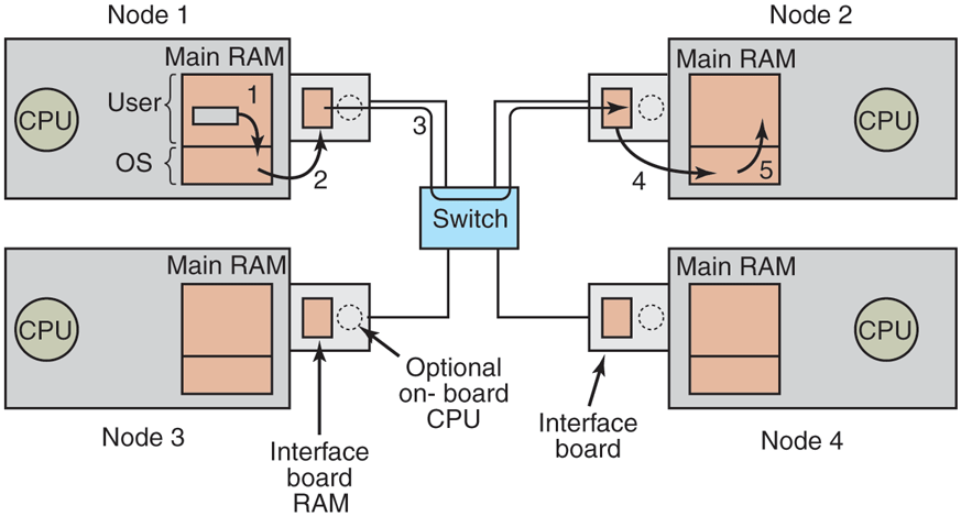
There are four nodes labeled node 1, node 2, node 3, and node 4 that are placed from top to bottom and left to right. A switch is placed in the center and connected with all nodes via lines. Node 1 is a squared block that contains C P U, on the left, and on the right, Main R A M is a vertical squared block placed with two partitions labeled User on the top and the O S on the bottom. The User partition has a small horizontal rectangular block with a downward arrow labeled 1 that points to the O S partition. There is an upward arrow labeled 2 from O S that points to the outer block that is connected to node 1. The outer block has a small vertical rectangular block labeled Interface board R A M on the left and a dotted circle labeled Optional onboard C P U on the right. Like node 1 structure, the other three nodes have the same structure. There is a forward arrow from the rectangular block placed in the outer block passing through the switch and pointing to the second rectangular block of the outer block of node 2. From the rectangular block point, a downward arrow labeled 4 points to the O S of node 2. From O S, an upward arrow labeled 4 points to the User block.
Back