Long description
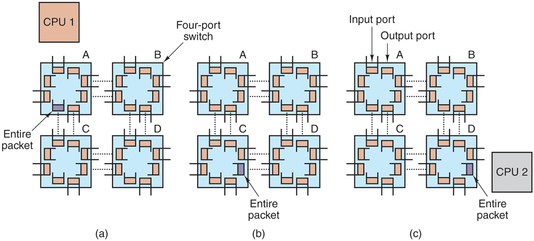
Part (a): There is a C P U 1 block on the top left. There are four-port switches labeled A, B, C, and D placed in two rows and two columns. All switches are connected via two dotted lines like A is connected to B, B to C, C to D, and D to A. In switch A, the entire packet is injected into the first switch by the source node’s network interface board and it is shown by highlighted one port. Part (b): There are four-port switches labeled A, B, C, and D placed in two rows and two columns respectively. All switches are connected via two dotted lines like A is connected to B, B to C, C to D, and D to A. The bits come in one at a time, and when the whole packet has arrived at an input buffer, it is copied to the line leading to the next switch along the path, as shown in switch C by highlighting the port. Part (c): There is a C P U 2 block on the bottom right. When the packet arrives at the switch attached to the destination node, as shown by highlighting one port in switch D, then the packet is copied to that node’s network interface board and eventually to its RAM.
Back