Long description
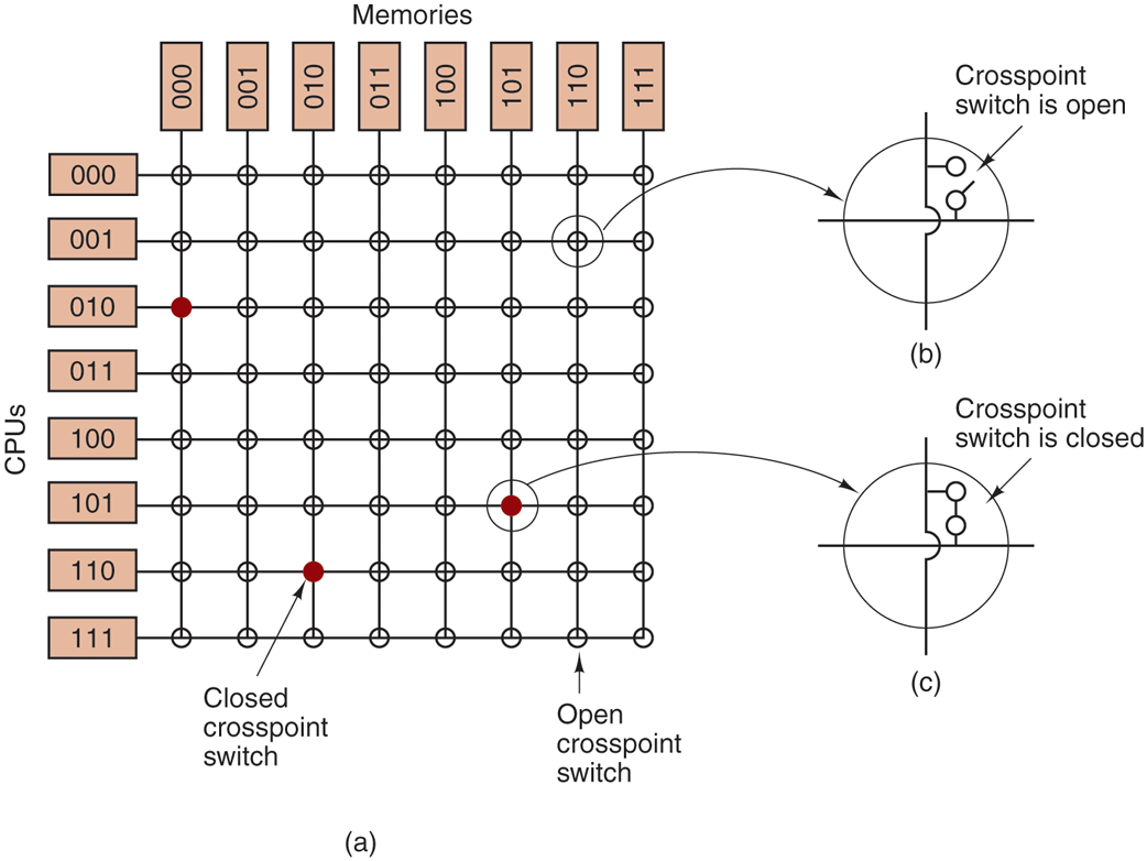
Part (a): The figure shows eight C P U blocks arranged vertically at the left. The C P U blocks from top to bottom are given as follows: 000, 001, 010, 011, 100, 101, 110, and 111. Six memory blocks are arranged horizontally from left to right at the upper end and are given as follows. 000, 001, 010, 011, 100, 101, 110 and 111. Horizontal lines are drawn from each C P U block and vertical lines are drawn from each memory block. These lines form a grid. The intersecting points are called cross-point switches, of which three are closed and others open. The magnified view of the open and closed switch are shown in part b and c. The switches are depicted by circles having a cross, and two open circles at the first quadrant of the cross. For an open switch, the two open circles are not connected, and for a closed switch the circles are connected. Part (b): An open node inside a circle is shown. The open position is labeled Crosspoint switch is open. Part (c): A closed node inside a circle is shown. The closed position is labeled Crosspoint switch is closed. Note: The open and closed switches marked in the part 1 points to the open and closed switches of parts b and c.
Back