Long description
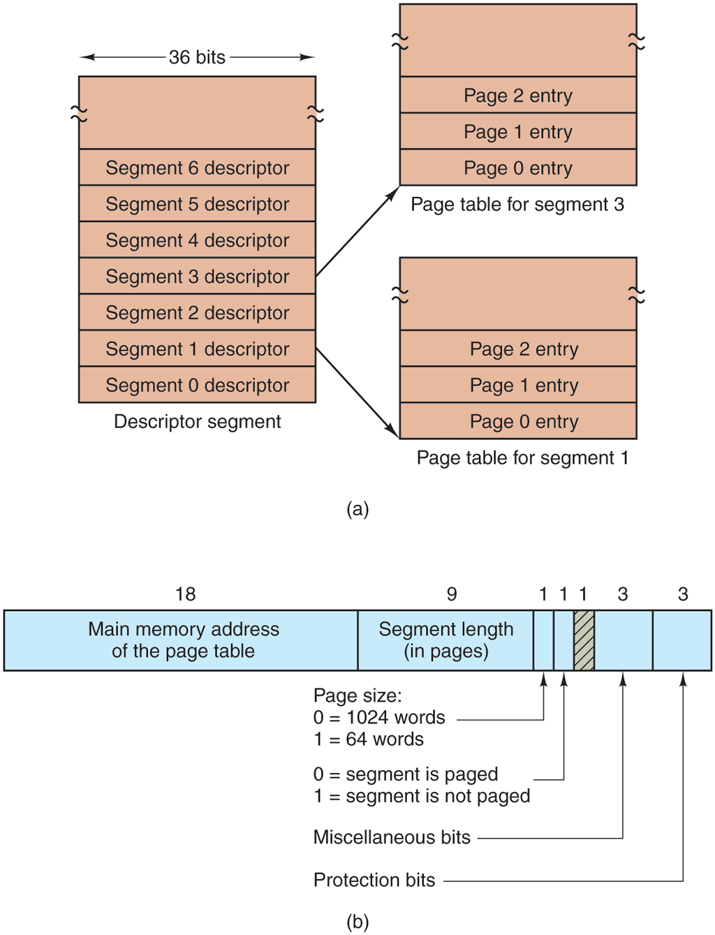
Part (a): The figure consists of three vertical blocks labeled descriptor segment, Page table for the segment 3 and Page table for the segment 1. The descriptor segment block having 36 bits consists of eight rows labeled from bottom to top as follows: Segment 0 descriptor, Segment 1 descriptor, Segment 2 descriptor, Segment 3 descriptor, Segment 4 descriptor, Segment 5 descriptor and Segment 6 descriptor.
The Page table for the segment 3 block consists of four rows labeled from bottom to top as follows. Page 0 entry, Page 1 entry, Page 2 entry, blank.
The Page table for the segment 1 block also consists of four rows labeled from bottom to top as follows. Page 0 entry, Page 1 entry, Page 2 entry, blank. The segment 3 descriptor row of the first block is connected to the page 0 entry of the second block. The segment 1 descriptor row of the first block is connected to page 0 entry of the third block.
Part (b): It consists of a horizontal block having seven columns labeled from left to right as follows: Main memory address of the page table, Segment length (in pages), blank, blank, blank, and is shaded, blank, blank.
The bits of the columns are marked 18, 9, 1, 1, 1, 3, 3.
The Page sizes of the columns except the first and second are given as follows. Column 3: 0 equals 1024 words and 1 equals 64 words.
Column 4: 0 equals segment is paged, 1 equals segment is not paged.
Column 6: Miscellaneous bits.
Column 7: Protection bits.
Back