Long description
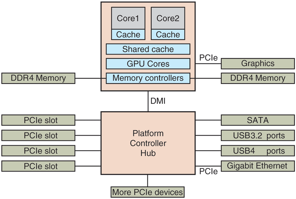
The image has two square-shaped shaded blocks at the center, one above the other. Five rectangular blocks are on the left of the two blocks, and six rectangular blocks are on the right of the two blocks. Center: In the center, the first square-shaped block has a further two square-shaped blocks with two partitions placed on the upper left and upper right labeled Core 1 and Cache, Core 2 and Cache from top to bottom partitions. There are three rectangle-shaped blocks in the first square placed top to bottom labeled Shared Cache, G P U Cores, and Memory Controllers. The second square-shaped block labeled Platform Controller Hub is placed at the bottom of the first square and both squares are connected with each other labeled D M I. There is a rectangular block under the second square, connected with it and labeled More P C I e devices. Left: The first rectangular block labeled DDR4 memory is connected to the first square. Four rectangular blocks labeled P C I e slot are connected to the second square. Right: Two rectangular blocks labeled Graphics, DDR4 memory, are connected to the first square via P C I e. The four rectangular blocks labeled S A T A, U S B 3.2 ports, U S B 4 ports, Gigabit Ethernet, and connected to the second square. The Gigabit Ethernet is connected to the second square via P C I e.
Back